【Notification of Manufacturer Change for Panasonic Industrial Devices SUNX Products and Panasonic Industrial Devices SUNX Tatsuno Products】
From April 1, 2024, the terms "Panasonic Industrial Devices SUNX Co., Ltd." and "Panasonic Industrial Devices SUNX Tatsuno Co., Ltd."
in this page and in the manuals and other documents to be downloaded will all be replaced with "Panasonic Industry Co., Ltd." and applied accordingly.
Safety door switch with key SG-B2
Cautions For Use
- In order to avoid electric shock or fire, turn the power off before installation, removal, wire connection, maintenance, or inspection of the safety switch.
- If relays are used in the circuit between the safety switch and the load, consider the danger and use safety relays, since welding or sticking contacts of standard relays may invalidate the functions of the safety switch.
- Do not place a PLC in the circuit between the safety switch and the load. Safety and security can be endangered in the event of a malfunction of the PLC.
- Do not disassemble or modify the safety switch, otherwise a breakdown or an accident may occur.
- Do not install the actuator in a location where the human body may come in contact. Otherwise injury may occur.
- Regardless of door types, do not use the safety switch as a door stop. Install a mechanical door stop at the end of the door to protect the safety switch against excessive force.
- Do not apply excessive shock to the safety switch when opening or closing the door. A shock to the safety switch exceeding 1,000 m/s2 may cause damage to the safety switch.
- If the operating atmosphere is contaminated, use a protective cover to prevent the entry of foreign objects into the safety switch through the actuator entry slots. Entry of a considerable amount of foreign objects into the safety switch may affect the mechanism of the safety switch and cause a malfunction.
- Cover the unused actuator entry slot using the slot plug supplied with the safety switch.
- Do not store the safety switches in a dusty, humid, or organic-gas atmosphere, or in an area subjected to direct sunlight.
- Use proprietary actuators only. When other actuators are used, the safety switch may be damaged.
Do not cut, machine, or otherwise modify actuators. Doing so may cause equipment failure.
- Do not open the lid of the safety switch. Loosening the screws may damage the safety switch.
- The locking strength is rated at 1,400 N. Do not apply a load higher than the rated value. When a higher load is expected, provide an additional system consisting of another safety switch without lock or a sensor to detect door opening and stop the machine.
- Regardless of door types, do not use the safety switch as a door lock. Install a separate lock using a latch or other measures.
- Although the SG-K21A / SG-K22A actuators alleviate the shock when the actuator enters the slot on the safety switch, make sure that excessive shock is not applied. If the rubber bushings become deformed or cracked, replace with new ones.
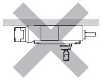
- Do not mount the safety switch facing down as shown in the figure below. Otherwise, the key may fall off due to shock.
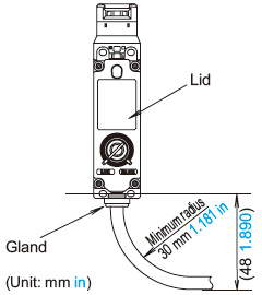
Cables
- Do not fasten or loosen the gland at the bottom of the safety switch.
- When bending the cable during wiring, make sure that the cable radius is kept at 30 mm 1.181 in minimum.
- When wiring, make sure that water or oil does not enter the cable.
- Do not open the lid of the safety switch. Otherwise the safety switch will be damaged.
|
|
Minimum radius of hinged door
When using the safety switch on hinged doors, refer to the minimum radius of doors shown below. When using on doors with small minimum radius, use the angle adjustable actuator (SG-K24).
| Note: |
Because deviation or dislocation of hinged doors may occur in actual applications, make sure of the correct operation before installation. |
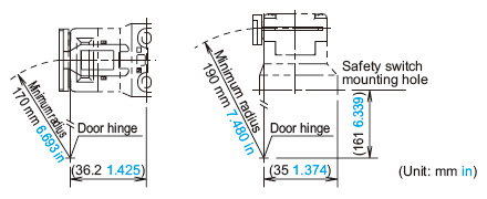
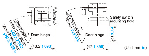
When using the right-angle actuator (SG-K22)
<When the door hinge is on the extension line of the actuator mounting surface> |
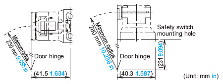 |
|
<When the door hinge is on the extension line of the safety switch surface> |
 |
|
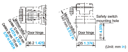
When using the right-angle actuator (with rubber bushings) (SG-K22A)
<When the door hinge is on the extension line of the actuator mounting surface> |
 |
|
<When the door hinge is on the extension line of the safety switch surface> |
 |
|
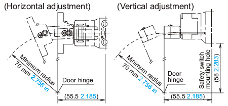
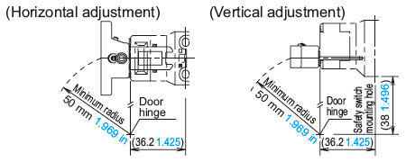
Actuator angle adjustment (vertical / horizontal)
- Using the angle adjustment screw (M3 hexagon-socket-head screw), the actuator angle can be adjusted. (refer to the dimensions)
Adjustable angle: 0 to 20°
- The larger the adjusted angle of the actuator, the smaller the applicable radius of the door opening. After installing the actuator, open the door. Then adjust the actuator so that its edge can be inserted properly into the actuator entry slot of the safety switch.
- After adjusting the actuator angle, apply Loctite to the adjustment screw so that the screw will not move.
When using the angle adjustable actuator (SG-K24)
- When the door hinge is on the extension line of the actuator mounting surface: 70 mm 2.756 in
- When the door hinge is on the extension line of the safety switch surface: 50 mm 1.969 in
<When the door hinge is on the extension line of the actuator mounting surface> |
 |
|
<When the door hinge is on the extension line of the safety switch surface> |
 |
|
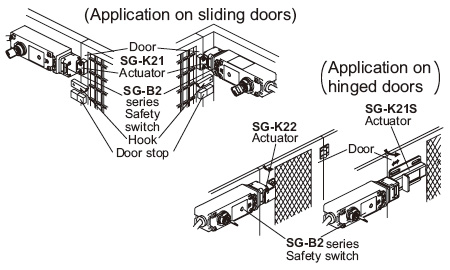
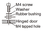
Mounting
- Mount the safety switch on a fixed piece of machinery or guard and the actuator on a hinged door.
Avoid mounting both the safety switch and actuator on a hinged door. Doing so may cause equipment failure. For more information about how to mount the devices, see the following diagram:
Recommended tightening torque for mounting screws
・Recommended screw tightening torque
| |
Screw tightening torque |
| For mounting the safety switch (M4 screw) (Note 1)
| 1.8~2.2N・m |
For mounting the actuator
(SG-K21 : Two M4 screws) (Note 1)
(SG-K21A / SG-K22A : Two M4 screws) (Note 1, 2)
(SG-K21S : M5 screw) (Note 1)
(SG-K22 : Two M4 phillips screws)
(SG-K24 : Two M4 screws) (Note 1)
|
1.8~2.2N・m
1.0~1.5N・m
4.5~5.5N・m
0.8~1.2N・m
1.0~1.5N・m |
| For mounting the SG-B2 head (M3)
| 0.9~1.1N・m |
| For mounting the manual rear unlocking button (M3 screw with washers)
| 0.5~0.7N・m |
Notes:
| 1) |
The above recommended tightening torques of the mounting screws are the values confirmed with hexagon-socket-head bolts. When other screws are used and tightened to a smaller torque, make sure that the screws do not come loose after mounting. |
| 2) |
In the case of SG-K21A or SG-K22A, using two M4 screws and two attached washers, fasten the actuator securely on the door.
 |
Return to top
Return to top

 Business
> Industrial Devices
> Automation Controls Top
> FA Sensors & Components
> Sensors
> Light Curtains / Safety Components
> Safety door switch with key SG-B2
> Cautions For Use
Business
> Industrial Devices
> Automation Controls Top
> FA Sensors & Components
> Sensors
> Light Curtains / Safety Components
> Safety door switch with key SG-B2
> Cautions For Use