【Notification of Manufacturer Change for Panasonic Industrial Devices SUNX Products and Panasonic Industrial Devices SUNX Tatsuno Products】
From April 1, 2024, the terms "Panasonic Industrial Devices SUNX Co., Ltd." and "Panasonic Industrial Devices SUNX Tatsuno Co., Ltd."
in this page and in the manuals and other documents to be downloaded will all be replaced with "Panasonic Industry Co., Ltd." and applied accordingly.
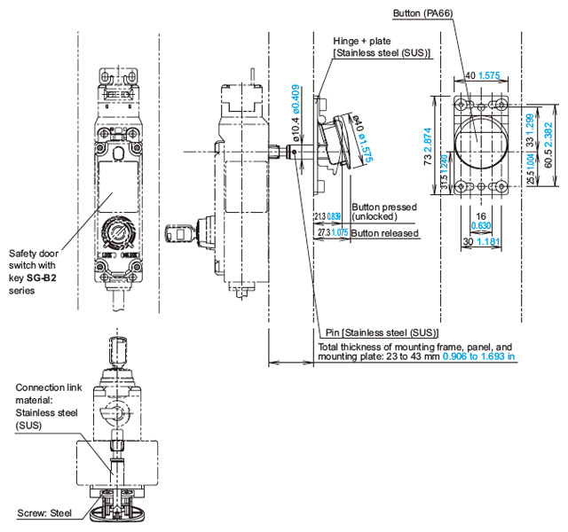
Safety door switch with key SG-B2
Dimensions
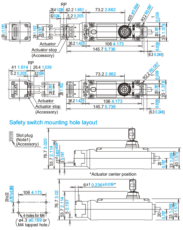
SG-B2-K2□-5
Door switch
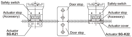
When using horizontal mounting / straight actuator (SG-K21) |
 |
|
When using vertical mounting / straight actuator (SG-K22) |
 |
|
Notes:
| 1) |
Plug the unused actuator entry slot using the plug supplied with the switch. |
| 2) |
When mounting the safety switch, be sure to conform to the mounting hole dimensions and secure in place with four screws. |
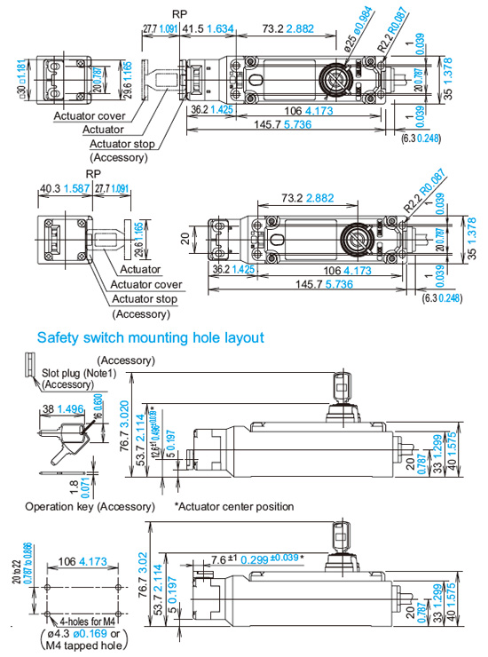
SG-B2-K2□-L5
Door switch (rear unlocking button type)
When using horizontal mounting / straight actuator (SG-K21) |
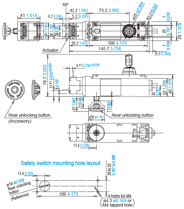 |
・Mounting part* thickness(X):1 to 6mm 0.039 to 0.236 in
6 < X < 23 mm 0.236 < X < 0.906 in : Not mountable
23 ≤ X ≤ 43 mm 0.906 ≤ X ≤ 2.087 in : Use a rear unlocking button kit.
* The mounting part is a frame or a panel that the product is mounted on.
・With the mounting hole dimension, the rear unlocking button rod does not touch the hole even when the safety switch moves sideways.
Note: Plug the unused actuator entry slot using the plug supplied with the switch. |
|
Actuator mounting reference position
As shown in the figure on the right, the mounting reference position of the actuator when inserted in the safety switch is:
The actuator stop on the actuator lightly touches the safety switch.
* The actuator stop is used to adjust the actuator position. Remove the actuator stop after the actuator position is mounted. |
|
Return to top
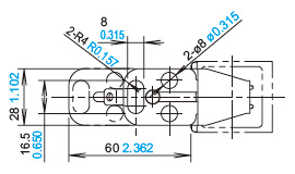
SG-K21
Straight actuator
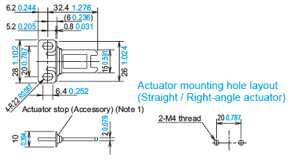 |
| Note: The actuator stop is used to adjust the actuator position. Remove the actuator stop after the actuator position is mounted. |
|
SG-K22
Right-angle actuator (SG-K22)
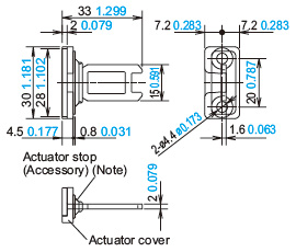 |
| Note: The actuator stop is used to adjust the actuator position. Remove the actuator stop after the actuator position is mounted. |
|
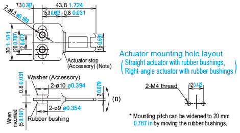
SG-K21A
Straight actuator with rubber bushings
Note:The actuator stop is used to adjust the actuator position. Remove the actuator stop after the actuator position is mounted.
| * |
Mounting pitch is set to 12 mm 0.472 in in factory. When setting the mounting pitch to 20 mm 0.787 in, widen the pitch of rubber cushions to 20 mm 0.787 in. |
| * |
The actuator has movement flexibility to the directions shown in (B). |
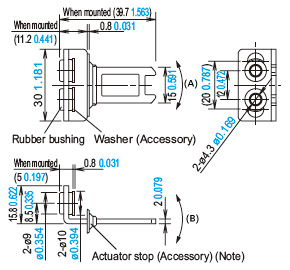
SG-K22A
Right-angle actuator with rubber bushings
Note:The actuator stop is used to adjust the actuator position. Remove the actuator stop after the actuator position is mounted.
| * |
When the mounting pitch is 12 mm 0.472 in (factory setting), the
actuator has movement flexibility to the directions shown in (A) and (B). |
| * |
When the mounting pitch is 20 mm 0.787 in, the actuator has
movement flexibility to the directions shown in (B). Side the rubber cushions together with the screws. |
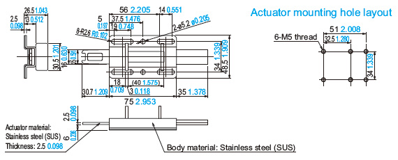
SG-K21S
SG-K24
Horizontal / Vertical angle adjustable actuators
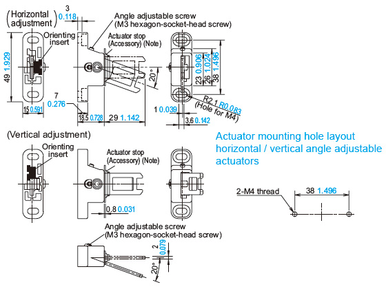 |
| Note: The actuator stop is used to adjust the actuator position. Remove the actuator stop after the actuator position is mounted. |
|
Changes in the orientation of adjustment for angle adjustable (vertical / horizontal) actuators
The orientation of adjustment of angle adjustable (vertical / horizontal) actuators is determined by the position in which the orienting insert (white plastic) is installed on the back of the actuator.
Install the insert according to the desired orientation of adjustment.
Exercise care not to lose the orienting insert. The actuator will not operate properly without the orienting insert.
Return to top
SG-PH2
MS-SG-21
Mounting plate (Optional)
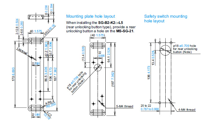 |
Material: Anodized aluminum A6063
Weight: Approx. 180 g
Note: With the mounting hole dimension, the rear unlocking button rod does not touch the hole even when the safety switch moves sideways. |
|
MS-SG-22
MS-SG-23
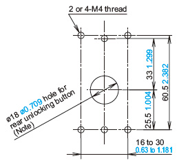
Rear unlocking button kit for a frame (Optional)
 |
| Note: With the mounting hole dimension, the rear unlocking button rod does not touch the hole even when the safety switch moves sideways. |
|
Rear unlocking button mounting dimensions |
 |
|
| Example: |
When mounted on a □30 mm □1.181 in frame using the mounting plate above MS-SG-21, select MS-SG-22 since the mounting part thickness (X) is 40 (X = 10 + 30 = 40) 1.575 (X = 0.394 + 1.181 = 1.575).
For more information about selecting a back manual unlocking button kit for a frame, see the following table: |
| Model No. |
Mounting part* thickness (X) (mm in) |
Rear unlocking button type
When installing an SG-B2-K2□D-L5 with
a rear unlocking button directly |
| MS-SG-22 |
33 < X ≤ 43 1.299 < X ≤ 1.693 |
| MS-SG-23 |
23 < X ≤ 33 0.906 < X ≤ 1.299 |
* The mounting part is a frame or a panel that the product is mounted on.
Return to top
Return to top

 Business
> Industrial Devices
> Automation Controls Top
> FA Sensors & Components
> Sensors
> Light Curtains / Safety Components
> Safety door switch with key SG-B2
> Dimensions
Business
> Industrial Devices
> Automation Controls Top
> FA Sensors & Components
> Sensors
> Light Curtains / Safety Components
> Safety door switch with key SG-B2
> Dimensions