[System Maintenance Notice]
Due to ongoing system maintenance, the site search and specification search functions are temporarily unavailable. We apologize for any inconvenience this may cause and appreciate your understanding.

 Business
> Industrial Devices
> Automation Controls Top
> FA Sensors & Components
> Motors for FA & Industrial Application
> AC Servo
> MINAS A5 Family(Discontinued Products)
> Wiring/ Connection
Business
> Industrial Devices
> Automation Controls Top
> FA Sensors & Components
> Motors for FA & Industrial Application
> AC Servo
> MINAS A5 Family(Discontinued Products)
> Wiring/ Connection
MINAS A5 Family(Discontinued Products)
|
We are sorry, the products have been discontinued. Please refer to the details of the discontinued products and the recommended substitutes list below.
|
|
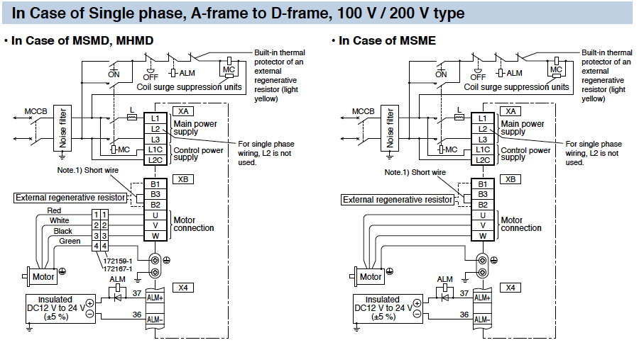
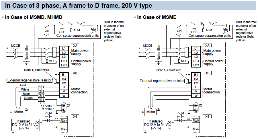
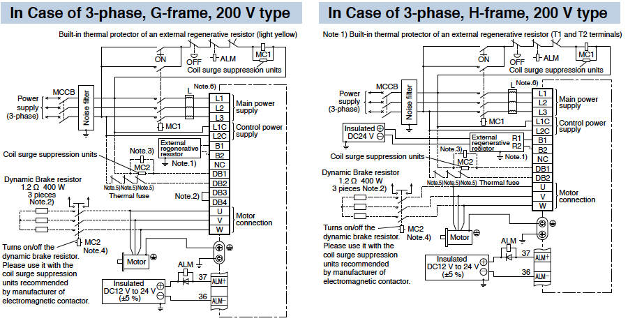
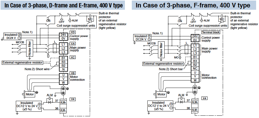
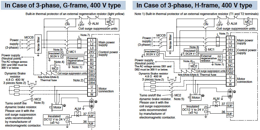
1.Wiring Diagram
Wiring to Connector, XA, XB, XC, XD and Terminal Block
|
||||||||||||||||||||||||||||||||||||||
|
||||||||||||||||||||||||||||||||||||||
|
||||||||||||||||||||||||||||

|
||||||||||||||||||||||||||||||||||||||||||||||||||||
|
||||||||||||||||||||||||||||
|
||||||||||||||||||||||||||||||||||||||||||||||||||||
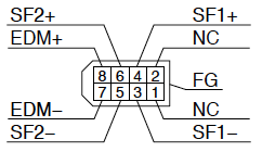
2.Safety Function
Wiring to the Connector, X3 (Excluding A5ⅡE, A5E Series)
Connecting the host controller can configure a safety circuit that controls the safety functions.
When not constructing the safety circuit, use the supplied safety bypass plug.
Outline Description of Safe Torque Off (STO)
|
Safety Precautions
|
|||||||||||||||||||||||||||||
●System configuration
|

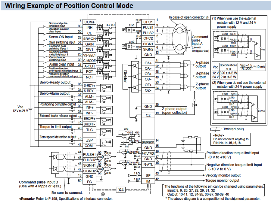
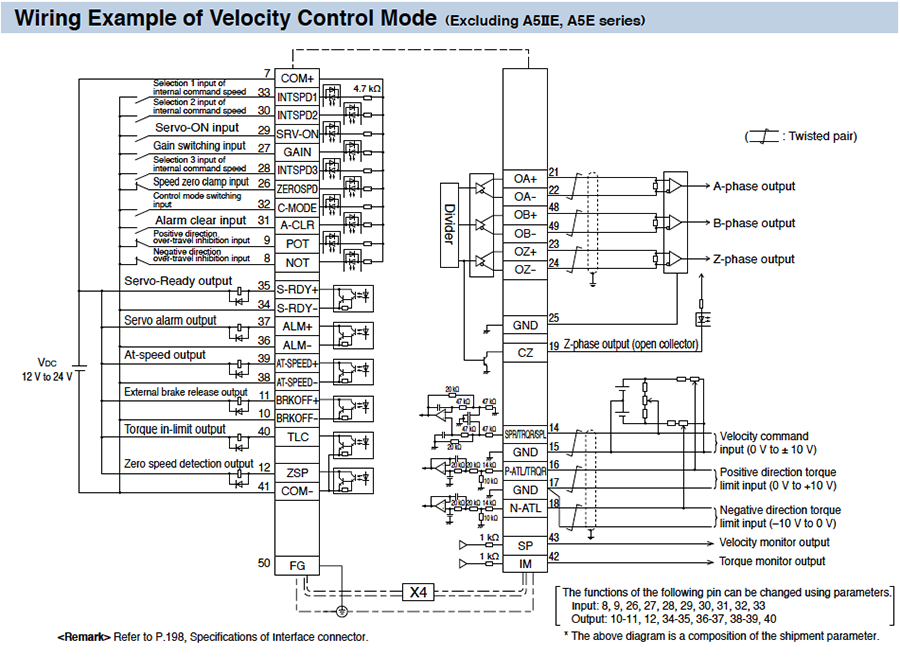
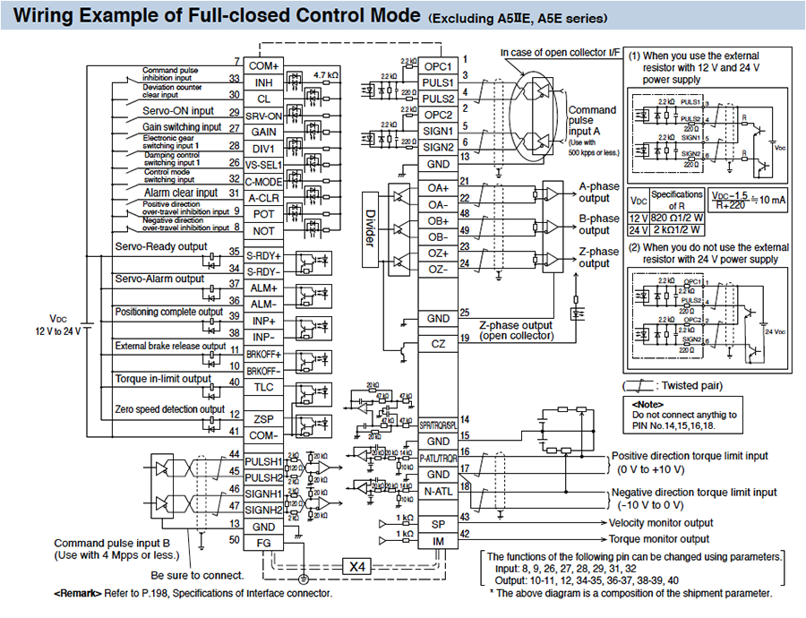
3.Control Circuit Diagram
Wiring to the Connector, X4
|
|
|

|
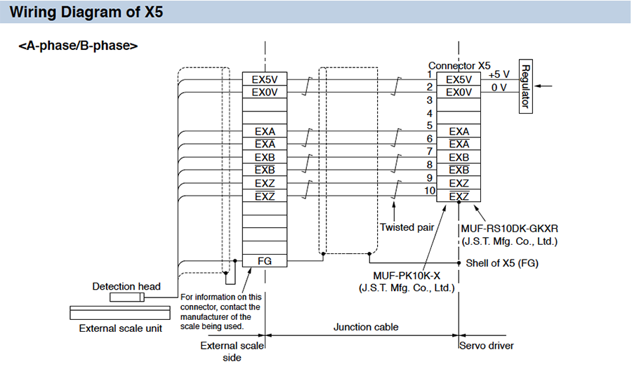
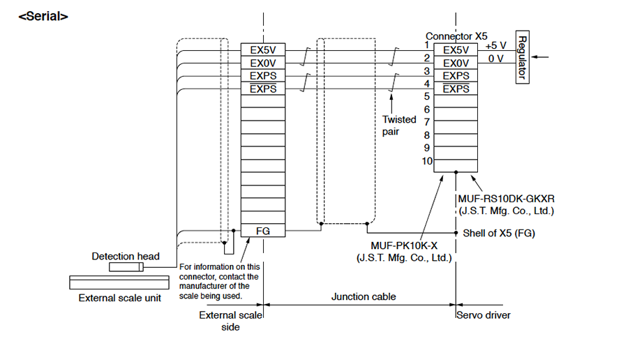
Wiring to the Connector, X5 (Excluding A5ⅡE, A5E series)
Applicable External Scale
|
|
|
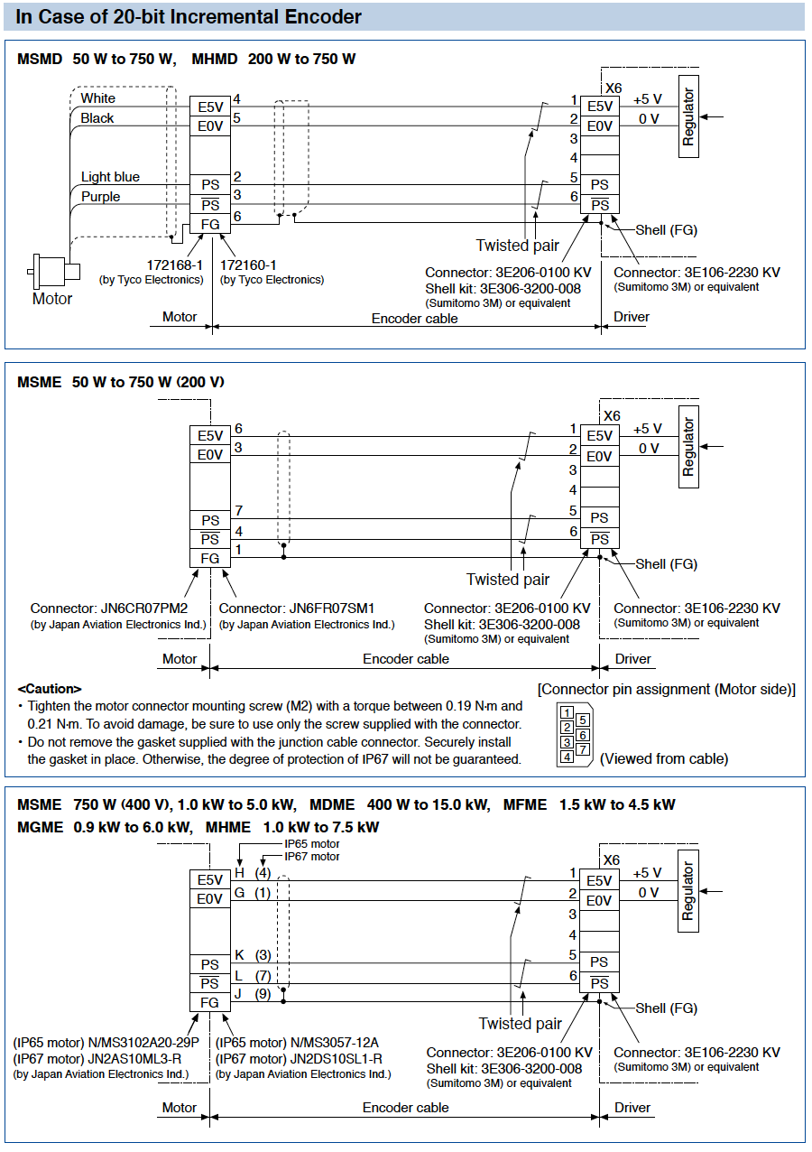
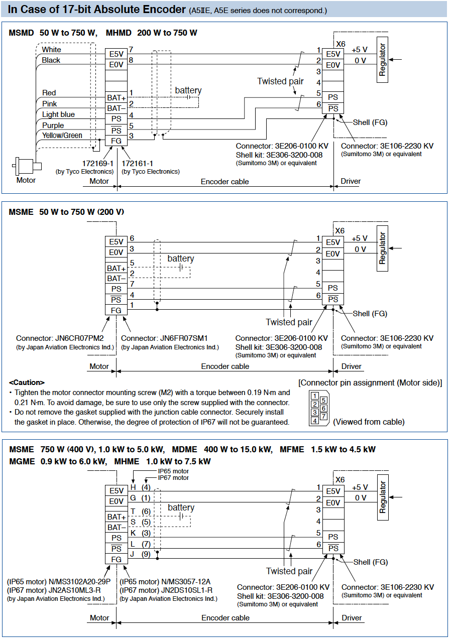
Wiring to the Connector, X6
|
|
Requests to customers (Automation Control Components & Industrial Device) [Excluding specific product]
Requests to customers (Automation Control Components & Industrial Device) [For specific product]
Requests to customers (FA Sensors & Components [Excluding motors])
Requests to customers (Dedicated to industrial motors)
- COMPONENTS & DEVICES
- FA SENSORS & COMPONENTS
- Fiber Sensors
- Photoelectric Sensors / Laser Sensors
- Micro Photoelectric Sensors
- Light Curtains / Safety Components
- Area Sensors
- Inductive Proximity Sensors
- Particular Use Sensors
- Sensor Options
- Wire-Saving Systems
- Programmable Controllers / Interface Terminal
- Human Machine Interface
- Pressure Sensors / Flow Sensors
- Measurement Sensors
- Static Control Devices
- Laser Markers / 2D Code Readers
- Machine Vision System
- Energy Management Solutions
- Timers / Counters / FA Components
- MOTORS
![]()