[System Maintenance Notice]
Due to ongoing system maintenance, the site search and specification search functions are temporarily unavailable. We apologize for any inconvenience this may cause and appreciate your understanding.

 Business
> Industrial Devices
> Automation Controls Top
> FA Sensors & Components
> Sensors
> Light Curtains / Safety Components
> Safety Control Unit SF-C21
> Part Number
> SF-C21
Business
> Industrial Devices
> Automation Controls Top
> FA Sensors & Components
> Sensors
> Light Curtains / Safety Components
> Safety Control Unit SF-C21
> Part Number
> SF-C21
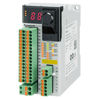
SF-C21 | Safety Control Unit SF-C21


|
*Photo may vary from actual product.

 This product has been confirmed that it does not contain the 6 substances specified in EU RoHS Directive 2011/65/EU and the 4 substances specified in 2015/863/EU.
| Product Number | SF-C21 |
| Part Number | SF-C21 |
| Product | Safety Control Unit |
| Product name | Safety Control Unit SF-C21 |
As of July 27, 2024
Specifications and design of the products are subject to change without notice for the product improvement.
Spec Detail
| Item | Specifications |
|---|---|
| Product Number | SF-C21 |
| Part Number | SF-C21 |
| Applicable standards : Safety | IEC 61508-1 to 3, EN 61508-1 to 3 (SIL3), ISO 13849-1:2015 (Category 4, PLe), IEC 61131-2, IEC 61010-2-201, IEC 62061 (SILCL3), UL 61010-1, UL 61010-2-201, UL 1998 |
| Applicable standards : EMC | IEC 61000-6-2, IEC 61326-3-1, EN 55011 |
| Related standards | IEC 60947-1, IEC 60947-5-1, IEC 60947-5-2, IEC 60947-5-5, IEC 60947-5-8, IEC 61496-1, IEC TS 62046, ISO 13851 |
| Applicable regulations and certifications | CE Marking (Machinery Directive, EMC Directive, RoHS Directive), UKCA Marking [Supply of Machinery (Safety)Regulations, EMC Regulations, RoHS Regulations], TÜV SÜD certification, Korea's Radio Waves Act conformity registration |
| Supply voltage : Power supply for internal | 24 V DC +10 -15 % Ripple P-P10 % or less (Note) "Power supply for internal" is the power supply for safety input. The power supplies for internal and external are insulated. (Note) The power supply unit connected to this device must satisfy the conditions below. - Output voltage within 20.4 V to 26.4 V DC (Ripple P-P: 10 % or less.) - Power supply unit SELV (safety extra low voltage) / PELV (protected extra low voltage) conforming to the EMC Directive and Low-voltage Directive (In case CE Marking conformity is required.) - Power supply unit conforming to the Low-voltage Directive and with an output of 100 VA or less - Power supply unit SELV (safety extra low voltage) / PELV (protected extra low voltage) conforming to the EMC Regulations and Low-voltage Regulations (In case UKCA Marking conformity is required.) - Power supply unit with an output holding time of 20 ms or more. - Power supply unit corresponding to CLASS 2 (In case C-TÜV US Listing Mark conformity is required.) |
| Supply voltage : Power supply for external | 24 V DC +10 -15 % Ripple P-P10 % or less (Note) "Power supply for external" is the power supply for control output / auxiliary output. The power supplies for internal and external are insulated. (Note) The power supply unit connected to this device must satisfy the conditions below. - Output voltage within 20.4 V to 26.4 V DC (Ripple P-P: 10 % or less.) - Power supply unit SELV (safety extra low voltage) / PELV (protected extra low voltage) conforming to the EMC Directive and Low-voltage Directive (In case CE Marking conformity is required.) - Power supply unit conforming to the Low-voltage Directive and with an output of 100 VA or less - Power supply unit SELV (safety extra low voltage) / PELV (protected extra low voltage) conforming to the EMC Regulations and Low-voltage Regulations (In case UKCA Marking conformity is required.) - Power supply unit with an output holding time of 20 ms or more. - Power supply unit corresponding to CLASS 2 (In case C-TÜV US Listing Mark conformity is required.) |
| Current consumption : Power supply for internal | 200 mA or less (Note) "Power supply for internal" is the power supply for safety input. The power supplies for internal and external are insulated. (Note) The power supply unit connected to this device must satisfy the conditions below. - Output voltage within 20.4 V to 26.4 V DC (Ripple P-P: 10 % or less.) - Power supply unit SELV (safety extra low voltage) / PELV (protected extra low voltage) conforming to the EMC Directive and Low-voltage Directive (In case CE Marking conformity is required.) - Power supply unit conforming to the Low-voltage Directive and with an output of 100 VA or less - Power supply unit SELV (safety extra low voltage) / PELV (protected extra low voltage) conforming to the EMC Regulations and Low-voltage Regulations (In case UKCA Marking conformity is required.) - Power supply unit with an output holding time of 20 ms or more. - Power supply unit corresponding to CLASS 2 (In case C-TÜV US Listing Mark conformity is required.) |
| Current consumption : Power supply for external | 100 mA or less (Note) "Power supply for external" is the power supply for control output / auxiliary output. The power supplies for internal and external are insulated. (Note) The power supply unit connected to this device must satisfy the conditions below. - Output voltage within 20.4 V to 26.4 V DC (Ripple P-P: 10 % or less.) - Power supply unit SELV (safety extra low voltage) / PELV (protected extra low voltage) conforming to the EMC Directive and Low-voltage Directive (In case CE Marking conformity is required.) - Power supply unit conforming to the Low-voltage Directive and with an output of 100 VA or less - Power supply unit SELV (safety extra low voltage) / PELV (protected extra low voltage) conforming to the EMC Regulations and Low-voltage Regulations (In case UKCA Marking conformity is required.) - Power supply unit with an output holding time of 20 ms or more. - Power supply unit corresponding to CLASS 2 (In case C-TÜV US Listing Mark conformity is required.) |
| Safety input (IN1 to IN8) | 2 inputs x 4, Rated voltage: Same as the voltage of the power supply for internal |
| Safety input (IN1 to IN8) : ON level | Input voltage: 18 V Input current: 3.5 mA |
| Safety input (IN1 to IN8) : OFF level | Input voltage: 5 V Input current: 1.0 mA |
| Safety input (IN1 to IN8) : Rated input current | 5 mA approx. |
| Safety input (IN1 to IN8) : Input impedance | 4.7 KΩ approx. |
| Safety input (IN1 to IN8) : Duration of detectable ON state | 10 ms or more |
| Safety input (IN1 to IN8) : Duration of undetectable OFF state | 0.7 ms or less |
| Control output (OUT1 to OUT4) | PNP open-collector transistor with 2 outputs x 2 - Maximum source current: 300 mA / output - Applied voltage: Same as the voltage of the power supply for external - Residual voltage: 2.5 V or less - Leakage current: 100 μA or less (Including power supply OFF condition) |
| Control output (OUT1 to OUT4) : Output mode | True: ON False: OFF |
| Control output (OUT1 to OUT4) : ON delay function | Incorporated |
| Control output (OUT1 to OUT4) : OFF delayfu nction | Incorporated |
| Control output (OUT1 to OUT4) : Short-circuit protection | Incorporated |
| Control output (OUT1 to OUT4) : Response time | OFF response: 10 ms or less ON response: 100 ms or less |
| Auxiliary output(AUX1 to AUX4)(Non-safety output) | PNP open-collector transistor with 1 output x 4 - Maximum source current: 60 mA / output - Applied voltage: Same as the voltage of the power supply for external - Residual voltage: 2.5 V or less - Leakage current: 100 μA or less (Including power supply OFF condition) |
| Auxiliary output(AUX1 to AUX4)(Non-safety output) : Output mode (Factory defaults) | AUX1: Negative logic of OUT1 / OUT2 (ON when OUT1 / OUT2 is OFF) AUX2: Negative logic of OUT3 / OUT4 (ON when OUT3 / OUT4 is OFF) AUX3: Reset trigger output (ON under reset release wait condition) AUX4: Lockout output (OFF when lockout) |
| Auxiliary output(AUX1 to AUX4)(Non-safety output) : Output mode (Any of the auxiliary outputs can be customized using the software tool) | Negative logic of OUT1 / OUT2 (ON when OUT1 / OUT2 is OFF) Negative logic of OUT3 / OUT4 (ON when OUT3 / OUT4 is OFF) Positive logic of OUT1 / OUT2 (ON when OUT1 / OUT2 is ON) Positive logic of OUT3 / OUT4 (ON when OUT3 / OUT4 is ON) Outputs A, B, C, and D of diagnosis results of input blocks (ON when logic is true) Outputs E, F, and G of internal logic circuit diagnostic results (ON when logic is true) Reset trigger output (ON under reset release wait condition) Lockout output (OFF when lockout) Muting indicator output (ON when muting / override) Monitor output in response to IN1 to IN8 (ON when input) No output (normally OFF) |
| Auxiliary output(AUX1 to AUX4)(Non-safety output) : Short-circuit protection | Incorporated |
| Auxiliary output(AUX1 to AUX4)(Non-safety output) : Response time | 10 ms or less |
| Muting indicator output | Semiconductor photo MOS relay output x 1 - Maximum load current: 60 mA - Supply voltage: Same as the voltage of the power supply for internal - Residual voltage: 2.5 V or less - Leakage current: 100 μA or less (Including power supply OFF condition) |
| Muting indicator output : Output mode | ON when muting / override |
| Muting indicator output : Short-circuit protection | Incorporated |
| Muting indicator output : Response time | 10 ms or less |
| Interlock function | Incorporated |
| Lockout release function | Incorporated |
| External device monitoring function | Incorporated |
| Communication function (MODBUS RTU) | Interface: RS-485 Protocol: MODBUS RTU Maximum transmission distance: 100 m 328.084 ft Maximum number of units that can be connected: 8 units (slaves) |
| Logic selection function | No.0: Customization control No.1: Overall stop control No.2: Parallel muting control No.3: Sequential muting control No.4: Partial stop control 1 No.5: Partial stop control 2 No.6: Two-hand control No.7: OR control No.8: Operation mode selection control |
| Logic setting function | Input mode, control mode, output mode, reset mode, auxiliary ou tput mode |
| Pollution degree | 2 |
| Excess voltage category | II |
| Operating altitude | 2,000 m 6561.680 ft or less (Note) Do not use or store this device in a pressurized environment beyond the atmospheric pressure at sea level. |
| Startup time after power on | 2 sec. or less |
| PFHD / MTTFD | 9.73 x 10⁻¹⁰ / 100 years or more |
| Environmental resistance:Degree of protection | IP20 (IEC)(must be installed in a control panel with protectio n IP54 or higher) |
| Environmental resistance:Ambient temperature | -10 to +55 ℃ +14 to +131 ℉ (No dew condensation or icing allowed), Storage: -25 to +60 ℃ -13 to +140 ℉ |
| Environmental resistance:Ambient humidity | 30 to 85 % RH, Storage: 30 to 85 % RH |
| Environmental resistance:Voltage withstandability | 1,000 V AC for one min. (All inputs connected together - USB port, all inputs connected together - RS-485 port, USB port - RS-485 port, between all supply terminals connected together and enclosure, all outputs connected together - all input connected together, all outputs connected together - USB port, all outputs connected together - RS-485 port) |
| Environmental resistance:Insulation resistance | 20 MΩ, or more, with 500 V DC megger (All inputs connected together - USB port, all inputs connected together - RS-485 port, USB port - RS-485 port, between all supply terminals connected together and enclosure, all outputs connected together - all input connected together, all outputs connected together - USB port, all outputs connected together - RS-485 port) |
| Vibration resistance | 5 to 8.4 Hz frequency, 3.5 mm 0.138 in half amplitude, 8.4 to 150 Hz frequency, Max. acceleration 9.8 m/s2 (1 G), in X, Y and Z directions for two hours each (IEC / EN 60068-2-6) |
| Environmental resistance:Shock resistance | 147 m/s2 (15 G) 11 ms in X, Y and Z directions for three times each (IEC / EN 60068-2-27) |
| Connecting method | Input / output and power supply: Detachable spring cage termina l blocks RS-485: Detachable spring-cage terminal block USB: Mini-B male |
| Cable length | 100 m 328.084 ft or less |
| Material | Main unit enclosure: Polycarbonate / ABS polymer alloy Enclosure: Polycarbonate |
| Weight | Net weight: 190 g approx. Gross weight: 320 g approx. |
Accessories (Option)

|
| Product Number | SFD-CC10 |
| Part Number | SFD-CC10 |
| Product name | Extension Cable |
|
|
| Product Number | SFD-CC10-MU |
| Part Number | SFD-CC10-MU |
| Product name | Extension Cable |
|
|
| Product Number | SFD-CC10-S |
| Part Number | SFD-CC10-S |
| Product name | Extension Cable |
Applicable Products
BY EMAIL
- U.S.A.
- +1-800-344-2112
- Europe
- +49-89-45354-1000
- China
- +86-10-59255988
- Singapore
- +65-6299-9181


Requests to customers (Automation Control Components & Industrial Device) [Excluding specific product]
Requests to customers (Automation Control Components & Industrial Device) [For specific product]
Requests to customers (FA Sensors & Components [Excluding motors])
Requests to customers (Dedicated to industrial motors)
- COMPONENTS & DEVICES
- FA SENSORS & COMPONENTS
- Fiber Sensors
- Photoelectric Sensors / Laser Sensors
- Micro Photoelectric Sensors
- Light Curtains / Safety Components
- Area Sensors
- Inductive Proximity Sensors
- Particular Use Sensors
- Sensor Options
- Wire-Saving Systems
- Programmable Controllers / Interface Terminal
- Human Machine Interface
- Pressure Sensors / Flow Sensors
- Measurement Sensors
- Static Control Devices
- Laser Markers / 2D Code Readers
- Machine Vision System
- Energy Management Solutions
- Timers / Counters / FA Components
- MOTORS
![]()