[System Maintenance Notice]
Due to ongoing system maintenance, the site search and specification search functions are temporarily unavailable. We apologize for any inconvenience this may cause and appreciate your understanding.

 Business
> Industrial Devices
> Automation Controls Top
> Components & Devices
> Relays / Couplers
> Power Relays (Over 2A)
> Power Relays (Over 2A) Lineup
> DJ-H Relays
> Rating/Performance
Business
> Industrial Devices
> Automation Controls Top
> Components & Devices
> Relays / Couplers
> Power Relays (Over 2A)
> Power Relays (Over 2A) Lineup
> DJ-H Relays
> Rating/Performance
DJ-H Relays
-
Lineup
-
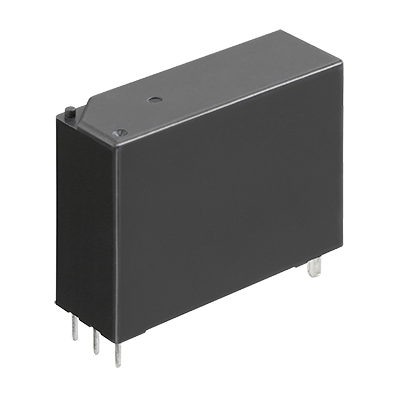
 DE Relays
Compliant with European safety standards, 1 Form A/2 Form A/1 Form A 1 Form B 10 A/8 A Polarized power relays
DE Relays
Compliant with European safety standards, 1 Form A/2 Form A/1 Form A 1 Form B 10 A/8 A Polarized power relays
-
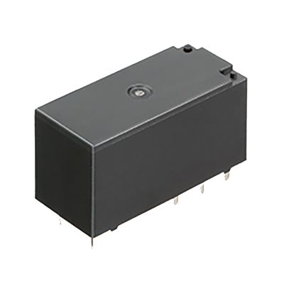
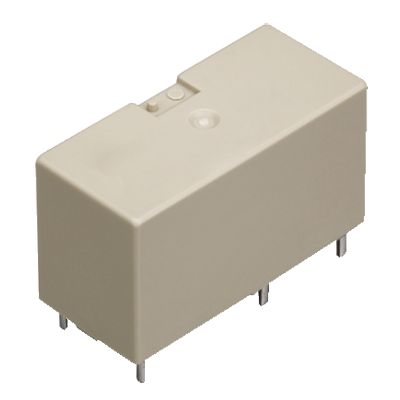 DJ Relays
High insulation, 1-pole/2-pole 16 A, Polarized power relays
DJ Relays
High insulation, 1-pole/2-pole 16 A, Polarized power relays
-
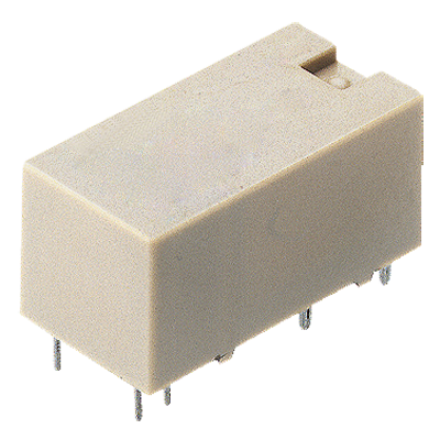
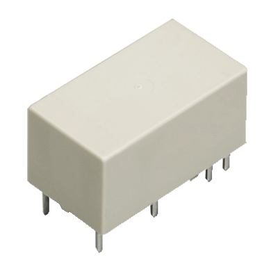
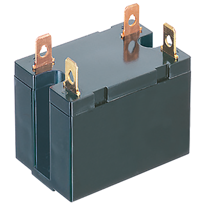
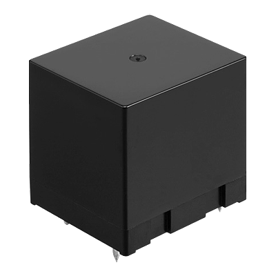
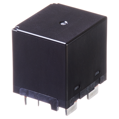
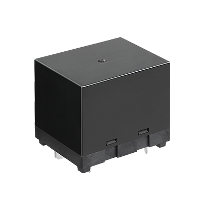
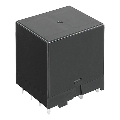
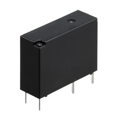
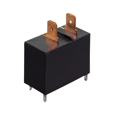
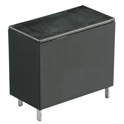
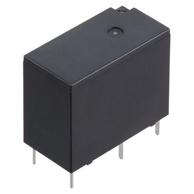
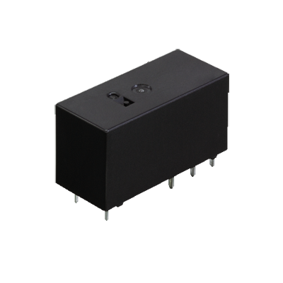
 DJ-H Relays
Suitable for lighting and motor load, 1 Form A 50 A, Latching relays
DJ-H Relays
Suitable for lighting and motor load, 1 Form A 50 A, Latching relays
-
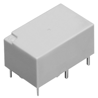 DK Relays
1 Form A 10 A, 1 Form A 1 Form B/2 Form A 8 A, Small polarized power relays
DK Relays
1 Form A 10 A, 1 Form A 1 Form B/2 Form A 8 A, Small polarized power relays
-
 DS Power Relays
1 Form A 8 A (AC) / 5 A (DC) , 1 Form A 1 Form B/2 Form A 5 A (AC/DC) , Small polarized power relays
DS Power Relays
1 Form A 8 A (AC) / 5 A (DC) , 1 Form A 1 Form B/2 Form A 5 A (AC/DC) , Small polarized power relays
-
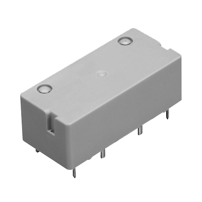
 DW Relays
1 Form A 8 A/16 A, Small, Polarized power relays (latching type)
DW Relays
1 Form A 8 A/16 A, Small, Polarized power relays (latching type)
-
 DY Relays
1 Form A 10 A, 1 Form A 1 Form B 8 A, Small polarized power relays
DY Relays
1 Form A 10 A, 1 Form A 1 Form B 8 A, Small polarized power relays
-
 DZ-S Relays
IEC62055-31 UC3 compliant, 1 Form A 90 A, Power latching relays
DZ-S Relays
IEC62055-31 UC3 compliant, 1 Form A 90 A, Power latching relays
-
 HE Relays
TV-10/TV-15 rated, 1 Form A 30 A, 2 Form A 25 A, Power relays
HE Relays
TV-10/TV-15 rated, 1 Form A 30 A, 2 Form A 25 A, Power relays
-
 HE Relays PV Type
Compact size, 1 Form A 35 A/48 A/90 A Power relays for solar inverter
HE Relays PV Type
Compact size, 1 Form A 35 A/48 A/90 A Power relays for solar inverter
-
 HE-A Relays
Compact size 1 Form A /1 Form A 1 Form B 110 A power relays for PV inverter, Charging station and Industrial equipment
HE-A Relays
Compact size 1 Form A /1 Form A 1 Form B 110 A power relays for PV inverter, Charging station and Industrial equipment
-
 HE-N Relays
High capacity 120 A 490 V AC 1 Form A power relay
HE-N Relays
High capacity 120 A 490 V AC 1 Form A power relay
-
 HE-S Relays
Compact size 2a and 2a1b 40 A power relays for energy management and industrial equipment
HE-S Relays
Compact size 2a and 2a1b 40 A power relays for energy management and industrial equipment
-
 HE-R Relays
Compact size 2 Form A and 2 Form A 1Form B 80 A/4 Form A and 4 Form A and 1 Form B 40 A power relays
HE-R Relays
Compact size 2 Form A and 2 Form A 1Form B 80 A/4 Form A and 4 Form A and 1 Form B 40 A power relays
-
 JV-N Relays
1 Form A 16 A, low profile: 10.9 mm power relays for heater control
JV-N Relays
1 Form A 16 A, low profile: 10.9 mm power relays for heater control
-
 JW Relays
1 Form A/1 Form C/2 Form A/2 Form C, 5 A/10 A, Power relays
JW Relays
1 Form A/1 Form C/2 Form A/2 Form C, 5 A/10 A, Power relays
-
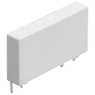
 LD-P Relays
Compliant with IEC/EN60335-1/ EN60079-15 (VDE approved) 1 Form A 5 A Slim power relays
LD-P Relays
Compliant with IEC/EN60335-1/ EN60079-15 (VDE approved) 1 Form A 5 A Slim power relays
-
 LF Relays
Ideal for compressor and inverter loads, 1 Form A 20 A, Power relays
LF Relays
Ideal for compressor and inverter loads, 1 Form A 20 A, Power relays
-
 LF-G Relays
Load for solar inverter, Compact size, 1 Form A 22 A/33 A, Power relays
LF-G Relays
Load for solar inverter, Compact size, 1 Form A 22 A/33 A, Power relays
-
 LQ Relays
Compliant with IEC/EN60335-1*1*2 /EN60079-15*3 1 Form A/1 Form C 10 A small power relays
LQ Relays
Compliant with IEC/EN60335-1*1*2 /EN60079-15*3 1 Form A/1 Form C 10 A small power relays
-
 LZ Relays
Low profile: 15.7 mm, 1 Form A/1 Form C 16 A, Power relay
LZ Relays
Low profile: 15.7 mm, 1 Form A/1 Form C 16 A, Power relay
-
 LZ-N Relays
EN60335-1 GWT compliant, 15.7 mm Low profile, 1 Form A/1 Form C 16 A, Power relays
LZ-N Relays
EN60335-1 GWT compliant, 15.7 mm Low profile, 1 Form A/1 Form C 16 A, Power relays
-
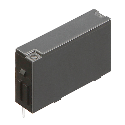
 NC Relays
Transistor drive, 2 Form C/4 Form C, 5 A Slim power relays
NC Relays
Transistor drive, 2 Form C/4 Form C, 5 A Slim power relays
-
 PA-N Relays
Complies with IEC61010 reinforced insulation, For PLC/Interface, 1 Form A 5 A, Slim power relay
PA-N Relays
Complies with IEC61010 reinforced insulation, For PLC/Interface, 1 Form A 5 A, Slim power relay
-
 PF Relays
Compliant with European standards, 1 Form A/1 Form C 6 A, Slim power relays
PF Relays
Compliant with European standards, 1 Form A/1 Form C 6 A, Slim power relays
-
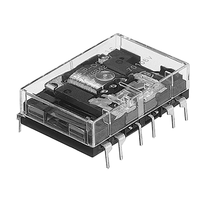
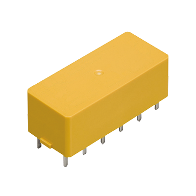 S Relays
2 Form A 2 Form B/3 Form A 1 Form B/4 Form A /4 A Polarized power relays
S Relays
2 Form A 2 Form B/3 Form A 1 Form B/4 Form A /4 A Polarized power relays
-
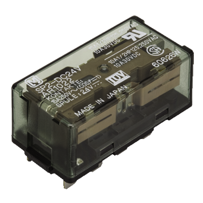 SP Relays
2 Form C 15 A, 4 Form C 10 A, Polarized power relays
SP Relays
2 Form C 15 A, 4 Form C 10 A, Polarized power relays
-
 ST Relays
1 Form A 1 Form B/2 Form A, 8 A, Polarized power relays
ST Relays
1 Form A 1 Form B/2 Form A, 8 A, Polarized power relays
-
- CAD data Catalogs/Datasheets
- FAQ
|
Coil data
- Operating characteristics such as 'Operate voltage' and 'Release voltage'
are influenced by mounting conditions, ambient temperature, etc.
Therefore, please use the relay within ±5% of rated coil voltage. - 'Initial' means the condition of products at the time of delivery.
1.1 coil latching
| Rated coil voltage |
Set voltage * (at 20°C) |
Reset voltage * (at 20°C) |
Rated operating current (±10%, at 20°C) |
Coil resistance (±10%, at 20°C) |
Rated operating power |
Max. allowable voltage (at 20°C) |
||
|---|---|---|---|---|---|---|---|---|
| Set coil |
Reset coil |
Set coil |
Reset coil |
|||||
| 5 V DC | Max. 75% V of rated coil voltage (Initial) |
Max. 75% V of rated coil voltage (Initial) |
200 mA | 200 mA | 25 Ω | 25 Ω | 1,000 mW | 130% V of rated coil voltage |
| 12 V DC | 83.3 mA | 83.3 mA | 144 Ω | 144 Ω | ||||
| 24 V DC | 41.7 mA | 41.7 mA | 576 Ω | 576 Ω | ||||
| * | square, pulse drive |
|---|
2.2 coil latching
| Rated coil voltage |
Set voltage * (at 20°C) |
Reset voltage * (at 20°C) |
Rated operating current (±10%, at 20°C) |
Coil resistance (±10%, at 20°C) |
Rated operating power |
Max. allowable voltage (at 20°C) |
||
|---|---|---|---|---|---|---|---|---|
| Set coil |
Reset coil |
Set coil |
Reset coil |
|||||
| 5 V DC | Max. 75% V of rated coil voltage (Initial) |
Max. 75% V of rated coil voltage (Initial) |
400 mA | 400 mA | 12.5 Ω | 12.5 Ω | 2,000 mW | 130% V of rated coil voltage |
| 12 V DC | 166.7 mA | 166.7 mA | 72 Ω | 72 Ω | ||||
| 24 V DC | 83.3 mA | 83.3 mA | 288 Ω | 288 Ω | ||||
| * | square, pulse drive |
|---|
Specifications
| Item | Specifications | |
|---|---|---|
| Contact data | Contact arrangement | 1 Form A |
| Contact resistance (initial) |
Max. 20 mΩ (by voltage drop 24 V DC 1 A) | |
| Contact material | AgSnO2 type | |
| Contact rating (resistive) |
50 A 277 V AC | |
| Max. switching power (resistive) |
13,850 VA(50 A 277 V AC) | |
| Max. switching voltage | 480 V AC | |
| Max. switching current | 50 A(AC) | |
| Min. switching load (reference value) *1 |
100 mA 5 V DC | |
| Insulation resistance (initial) | Min. 1,000 MΩ (at 500 V DC, Measured portion is the same as the case of dielectric strength.) |
|
| Dielectric strength (initial) |
Between open contacts |
1,500 Vrms for 1 min (detection current: 10 mA) |
| Between contact and coil |
4,000 Vrms for 1 min (detection current: 10 mA) | |
| Surge withstand voltage (initial) *2 |
Between contact and coil |
12,000 V |
| Time characteristics (initial) |
Set time | Max. 20 ms at rated coil voltage (at 20°C, without bounce) |
| Reset time | Max. 20 ms at rated coil voltage (at 20°C, without bounce) | |
| Shock resistance |
Functional | 100 m/s2 (half-sine shock pulse: 11 ms, detection time: 10 µs) |
| Destructive | 1,000 m/s2 (half-sine shock pulse: 6 ms) | |
| Vibration resistance |
Functional | 10 to 55 Hz (at double amplitude of 1.5 mm, detection time: 10 µs) |
| Destructive | 10 to 55 Hz (at double amplitude of 2 mm) | |
| Expected life | Mechanical life | Min. 106 ope. (switching frequency: at 180 times/min) |
| Conditions | Conditions for usage, transport and storage *3 |
Ambient temperature: -40 to +85°C (Allowable temperature is from -40 to +70°C at our standard packing condition.) Humidity: 5 to 85% RH (Avoid icing and condensation) |
| Unit weight | Approx. 31 g | |
| *1 | This value can change due to the switching frequency, environmental conditions, and desired reliability level, therefore it is recommended to check this with the actual load. |
|---|---|
| *2 | Wave is standard shock voltage of ±1.2 x 50 µs according to JEC-212-1981 |
| *3 | For ambient temperature, please read "GUIDELINES FOR RELAY USAGE". |
Expected electrical life
Conditions: Switching frequency ON : OFF = 1 s : 9 s
| Type | Load | Switching capacity | Number of operations | |
|---|---|---|---|---|
| 1 Form A | Resistive load | 25 A 277 V AC | Min. 100 x 103 ope. | |
| 50 A 277 V AC | Min. 10 x 103 ope. | |||
| Inrush resistance current load |
Tungsten load | 2,400 W 120 V AC | Min. 25 x 103 ope. (switching frequency ON : OFF = 1 s : 59 s) |
|
| Electronic ballast load | 20 A 277 V AC | Min. 6 x 10³ ope. | ||
| Capacitive load (IEC 60669-1) |
20 A 250 V AC 200 µF | Min. 30 x 103 ope. | ||
Inrush load (Electrical life diagram)
| Load | Tungsten load | Electronic ballast load | Capacitive load (IEC 60669-1) |
|---|---|---|---|
| Switching capacity | 2,400 W 120 V AC | 20 A 277 V AC | 20 A 250 V AC 200 µF |
| Load voltage | 120 V AC (60 Hz) | 277 V AC (60 Hz) | 250 V AC (60 Hz) |
| Load current | Inrush: 250 AO-P, Steady-state: 20 Arms |
Inrush: 480 AO-P, Steady-state: 16 Arms |
Inrush: 400 AO-P, Steady-state: 20 Arms |
| Circuit |  |
 |
 |
| Inrush current waveform |
 |
 |
 |
|
BY EMAIL


Requests to customers (Automation Control Components & Industrial Device) [Excluding specific product]
Requests to customers (Automation Control Components & Industrial Device) [For specific product]
Requests to customers (FA Sensors & Components [Excluding motors])
Requests to customers (Dedicated to industrial motors)
- COMPONENTS & DEVICES
- FA SENSORS & COMPONENTS
- Fiber Sensors
- Photoelectric Sensors / Laser Sensors
- Micro Photoelectric Sensors
- Light Curtains / Safety Components
- Area Sensors
- Inductive Proximity Sensors
- Particular Use Sensors
- Sensor Options
- Wire-Saving Systems
- Programmable Controllers / Interface Terminal
- Human Machine Interface
- Pressure Sensors / Flow Sensors
- Measurement Sensors
- Static Control Devices
- Laser Markers / 2D Code Readers
- Machine Vision System
- Energy Management Solutions
- Timers / Counters / FA Components
- MOTORS
![]()