
 Business
> Industrial Devices
> Automation Controls Top
> Components & Devices
> Switches
> Non Seal Type Switches
> AEQ (EQ) Switches
> Cautions For Use
Business
> Industrial Devices
> Automation Controls Top
> Components & Devices
> Switches
> Non Seal Type Switches
> AEQ (EQ) Switches
> Cautions For Use
AEQ (EQ) Switches
-
Lineup
-
 AV6 (CS) Switches
Subminiature Size Connector Integrated Type
AV6 (CS) Switches
Subminiature Size Connector Integrated Type
-
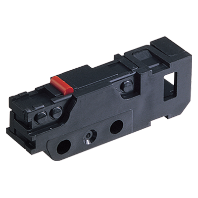
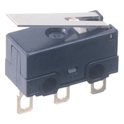
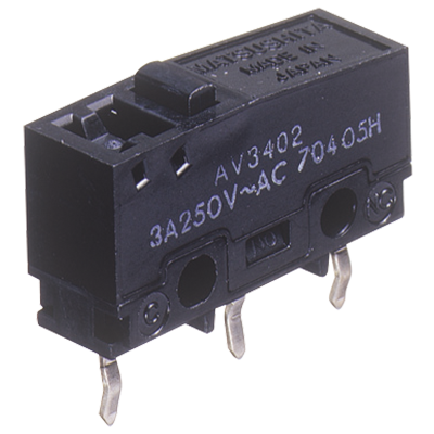
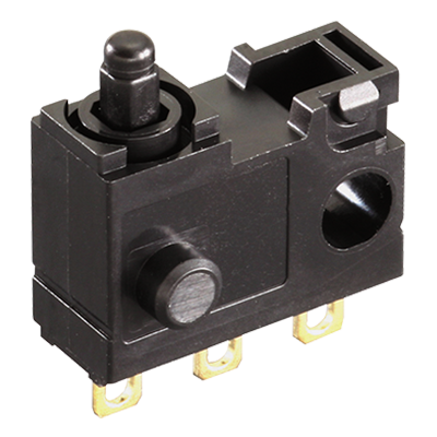 AEQ (EQ) Switches
Sliding contact construction Switches for Low-level Loads
AEQ (EQ) Switches
Sliding contact construction Switches for Low-level Loads
-
 AH1 (FJ) Switches
Ultra-miniature Size Switches High Precision
AH1 (FJ) Switches
Ultra-miniature Size Switches High Precision
-
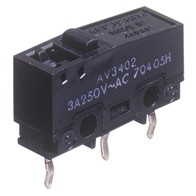
 AV3/AVM3 (FS) Switches
Subminiature Size Switches with Excellent Operating Position Accuracy
AV3/AVM3 (FS) Switches
Subminiature Size Switches with Excellent Operating Position Accuracy
-
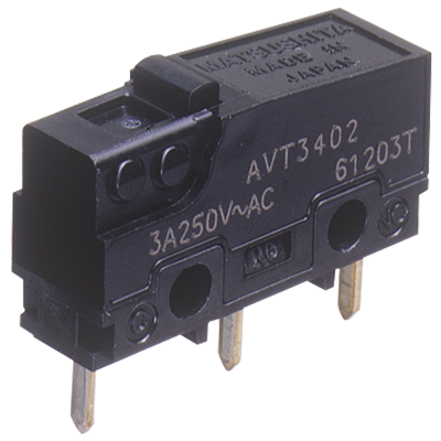 AVT3/AVL3 (FS-T) Switches
Subminiature Size Switches with Excellent Operating Position Accuracy
AVT3/AVL3 (FS-T) Switches
Subminiature Size Switches with Excellent Operating Position Accuracy
-
 AV3 (FS) Switches Contact gap 1 mm Type
Subminiature Size Door Inter-lock Switches
AV3 (FS) Switches Contact gap 1 mm Type
Subminiature Size Door Inter-lock Switches
-
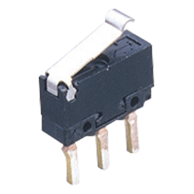 AV4 (FU) Switches
Ultra-miniature Size, Light-weight Snap action Switches
AV4 (FU) Switches
Ultra-miniature Size, Light-weight Snap action Switches
-
- CAD data Catalogs/Datasheets
- FAQ
|
AEQ (EQ) Switches Cautions For Use
1.Soldering conditions
The application of excessive heat upon the switch when soldering can cause degradation of switch operation. Therefore, be sure to keep within the conditions given below. Manual soldering: use soldering irons (Max. 350°C, within 3 seconds at each terminal) capable of temperature adjustment. This is to prevent deterioration due to soldering heat. Care should be taken not to apply force to the terminals during soldering. (More than one second interval is required to apply heat at each terminal.) Please consult us if you intend to use a soldering iron that exceeds 60 W.
2.Mounting
Please avoid use in which load would be applied to the sides [hatch part (both sides) shown below] of the switch in the direction indicated by the arrows. This could cause erroneous operation. Also, when using a metal installation board, please make allowance for burr direction designation and burr suppressing, etc., so that the burr side will not be on the switch installation side.
|
- 1.To secure the switch, please use an M3 small screw on a flat surface and tighten using a maximum torque of 0.29N·m. It is recommended that spring washers be used with the screws and adhesive be applied to lock the screws to prevent loosening of the screws. Please make sure not to apply adhesive onto the moving parts.
- 2.Be sure to maintain adequate insulating clearance between each terminal and ground.
- 3.Although it is possible to directly operate the pin plunger type from the lateral direction, please consult us if doing so.
- 4.After mounting please make sure no tensile load will be applied to the switch terminals.
- 5.Range of possible use: Please set the operation position to within the ranges in the following table so that there is sufficient insulation distance and to maintain contact reliability.
- 6.P/C board terminal type should be used if the products are to be soldered on the P/C board. (Solder terminal type is not for soldering on P/C board.)
| Actuator | Plunger/lever free | |
|---|---|---|
| From boss and hole center line | From standoff | |
| Pin plunger | >9.2 mm | >13.4 mm |
| Leaf lever | >10.7 mm | >14.9 mm |
| Simulated leaf lever | >13.5 mm | >17.7 mm |
| Actuator | Plunger/Lever pushed | |
|---|---|---|
| From boss and hole center line | From standoff | |
| Pin plunger | 7.8 to 5.9 mm | 12.0 to 10.1 mm |
| Leaf lever | 8.4 to 6.2 mm | 12.6 to 10.4 mm |
| Simulated leaf lever | 11.1 to 8.7 mm | 15.3 to 12.9 mm |
3.Cautions regarding the circuit
- 1.In order to prevent malfunction in set devices caused by bounce and chattering during the ON-OFF switch operation, please verify the validity of the circuit under actual operating conditions and temperature range.
- 2.When switching inductive loads (relays, solenoids, buzzers, etc.), an arc absorbing circuit is recommended to protect the contacts.
4.Please verify under actual conditions.
Please be sure to conduct quality verification under actual operating conditions in order to increase reliability during actual use.
5.Selection of switch
Please make your selection so that there will be no problems even if the operating characteristics vary up to ±20% from the standard values.
6.Other
- 1.Keep away from environments where silicon based adhesives, oil or grease are present as faulty contacts may result from silicon oxide. Do not use in areas where flammable or explosive gases from gasoline and thinner, etc., may be present.
- 2.When using the lever type, please be careful not to apply unreasonable load from the reverse or lateral directions of operation.
- 3.Do not exceed the total travel position (TTP) and press the actuator. This could cause operation failure. Also, when switching at high speed or under shock even within the operation limit, the working life may decrease. Therefore, please be sure to verify the quality under actual conditions of use.
- 4.Please make considerations so that the switch does not become the stopper for the operating part. The switch could break.
|
Related Information
BY EMAIL
- U.S.A.
- +1-800-344-2112
- Europe
- +49-89-45354-1000
- China
- +86-10-59255988
- Singapore
- +65-6299-9181


Requests to customers (Automation Control Components & Industrial Device) [Excluding specific product]
Requests to customers (Automation Control Components & Industrial Device) [For specific product]
Requests to customers (FA Sensors & Components [Excluding motors])
Requests to customers (Dedicated to industrial motors)
- COMPONENTS & DEVICES
- FA SENSORS & COMPONENTS
- Fiber Sensors
- Photoelectric Sensors / Laser Sensors
- Micro Photoelectric Sensors
- Light Curtains / Safety Components
- Area Sensors
- Inductive Proximity Sensors
- Particular Use Sensors
- Sensor Options
- Wire-Saving Systems
- Programmable Controllers / Interface Terminal
- Human Machine Interface
- Pressure Sensors / Flow Sensors
- Measurement Sensors
- Static Control Devices
- Laser Markers / 2D Code Readers
- Machine Vision System
- Energy Management Solutions
- Timers / Counters / FA Components
- MOTORS
![]()