If the surface mount terminal relay is mounted on a printed circuit board under incorrect conditions, the function may be damaged.
The following describes some cautions required for surface mount relay installation to prevent soldering troubles.
Our company safety relays do not have surface-mount terminal relays.
1. About Surface Mount Relay
■From IMT to SMT
Conventional insertion mount technology (IMT) is now being replaced with surface mount technology (SMT).
Solid-state components such as resistors, ICs, and diodes can withstand high heat stresses from reflow soldering because they use no mechanical parts.
In contrast, the conventional electromechanical relays consisting of solenoid coils, springs, and armatures are very sensitive to thermal stress from reflow soldering.
We applied the experience gained from our advanced relay technologies to produce high-performance electromagnetic relays compatible with surface mount technologies such as IRS and VPS.
Insertion Mount Technology (IMT) vs. Surface Mount Technology (SMT)
| Insertion Mounting Technology: IMT |
Components' leads are inserted into lead holes drilled into the PC board and are soldered to copper pads on the other side of the board using flow-soldering techniques. |
 |
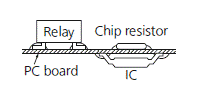
| Surface Mounting Technology: SMT |
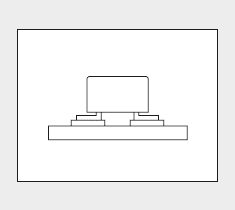
Components are placed on copper pads precoated with paste solder and the board assembly is heated to solder the components on the pads (reflow soldering). |
 |
■Features and Effects
| Features |
Effects |
• Allows high density mounting
• Components can be installed on both sides of a board
• Ceramic PC boards can be used |
System downsizing |
• Compatible with automatic placement by robots
• Drilling for lead holes is not required
• Compact system designs are possible due to high density mounting |
Overall cost reduction |
• High heat resistance
• Anti-gas measures |
High reliability |
The surface mount relay is manufactured with the following advanced technologies:
- Heat-resistance encapsulation technique
- Gas analysis
- Reliability assessment
- Precision molding technique for heat-resistant materials
■Examples of SMT Applications
The following describes some examples of typical SMT applications:
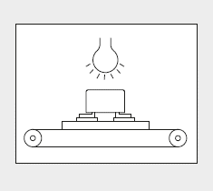
1. Infrared Reflow Soldering (IRS)
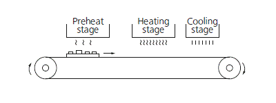
IRS is the most popular reflow soldering technology now available for surface mounting. It uses a sheath heater or infrared lamp as its heat source.
PC board assemblies are continuously soldered as they are transferred through a tunnel furnace comprised of a preheating, heating, and cooling-stages. |
 |
|
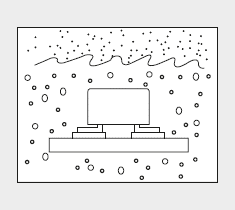
2. Vapor Phase Soldering (VPS)
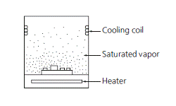
With VPS technology, PC board assemblies are carried through a special inactive solvent, such as Fluorinert FC-70, that has been heated to a vapor state.
As the saturated vapor condenses on the PC board surface, the resulting evaporation heat provides the energy for reflow soldering. |
 |
|
3. Belt conveyer reflow furnace
As PC board assemblies are transferred on a thin, heatresistant belt conveyer, they are soldered by the heat from hotplates placed begeath the conveyer belt.
4. Double Wave Soldering (DWS)
Components are glued to the PC board surface. The board assembly is transferred through a molten solder fountain (with the component side facing down), and the components are soldered to the board.
5. Other technologies
Other reflow soldering technologies include those utilizing lasers, hot air, and pulse heaters.
2. Cautions for Installation
■Paste Soldering
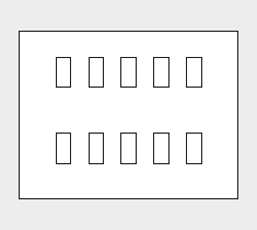
- Mounting pads on PC boards must be designed to absorb placement errors while taking account of solderability and insulation. Refer to the suggested mounting pad layout in the application data for the required relay product.
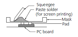
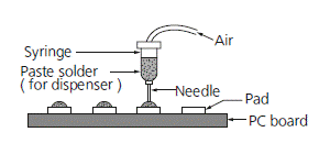
- Paste solder may be applied on the board with screen printing or dispenser techniques. For either method, the paste solder must be coated to appropriate thickness and shapes to achieve good solder wetting and adequate insulation.
Screen Printing
Solder Dispenser
■Relay Installation
- For small, lightweight components such as chip components, a self-alignment effect can be expected if small placement errors exist.
However, this effect is not as expected for electro-mechanical components such as relays, and they require precise positioning on their soldering pads.
- If SMT relays sustain excessive mechanical stress from the placement machine's pickup head, their performance cannot be guaranteed.
- Our SMT relays are supplied in stick packaging compatible with automatic placement processes. We also offer tape packaging at customer request.
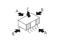
ex. TQ-SMD Relay
[Chucking pressure]
Direction A: MAX. 9.8 N (1 kgf)
Direction B: MAX. 9.8 N (1 kgf)
Direction C: MAX. 9.8 N (1 kgf) |
 |
|
■Reflow
- Reflow soldering under inadequate soldering conditions may result in unreliable relay performance or even physical damage to the relay (even if the relay is of surface mount type with high heat resistance).
- It is recommended that the soldered pad be immediately cooled to prevent thermal damage to the relay and its associated components.
- While surface mount relays are solvent washable, do not immerse the relay in cold cleaning solvent immediately after soldering.
Example of Recommended Soldering Condition for Surface Mount Relays.
 |
t1 = 60 s to 120 s
t2 = within 20 s
t3 = within 30 s
t4 = within 10 s (245 to 250°C)
|
T1 = 150 ~ 180°C
T2 = 230°C and higher
T3 = 250°C max
|
|
- Measuring position of temperature profile
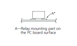 |
* The soldering temperature profile indicates the pad temperature. In some cases, the ambient temperature may be greatly increased. Check for the specific mounting condition. |
|
| Soldering iron wattage |
30 to 60 W |
| Soldering iron tip temperature |
350°C |
| Soldering time |
Less than 3 s |
When a soldering technique other than above is to be used (hot air, hotplate, laser, or pulse heater technique), carefully investigate the suitability of the technique.
| Note) |
|
Crawlability, wettability, and solder strength vary depending on the mounting conditions and the type of solder. Please evaluate under actual production conditions. |
■Cooling・Cleaning
- While surface mount relays are solvent washable, do not immerse the relay in cold cleaning solvent immediately after soldering.
- The surface mount relays are solvent washable. Use alcohol or an equivalent solvent for cleaning.
- Boiled cleaning is approved for surface mount relays. Ultrasonic cleaning may cause coil damage or light contact sticking.
Return to top
 Business
> Industrial Devices
> Automation Controls Top
> Components & Devices
> Relays / Couplers
> Cautions for Surface Mount Relay Installation


