[System Maintenance Notice]
Due to ongoing system maintenance, the site search and specification search functions are temporarily unavailable. We apologize for any inconvenience this may cause and appreciate your understanding.

 Business
> Industrial Devices
> Automation Controls Top
> Components & Devices
> Relays / Couplers
> Solid State Relays
> Solid State Relays Lineup
> AQ-J Solid State Relay
> Rating/Performance
Business
> Industrial Devices
> Automation Controls Top
> Components & Devices
> Relays / Couplers
> Solid State Relays
> Solid State Relays Lineup
> AQ-J Solid State Relay
> Rating/Performance
AQ-J Solid State Relay
-
Lineup
-
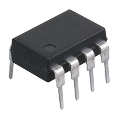
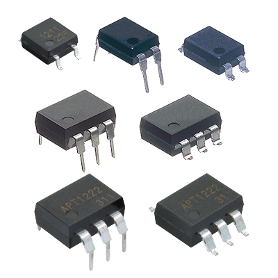 Phototriac Coupler
Phototriac coupler for the industrial machinery and consumer electronics
Phototriac Coupler
Phototriac coupler for the industrial machinery and consumer electronics
-
 AQ1 Solid State Relay
High capacity up to 3 A/10 A PC board terminal type
AQ1 Solid State Relay
High capacity up to 3 A/10 A PC board terminal type
-
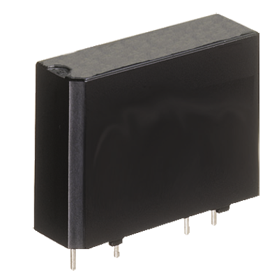
 AQ8 Solid State Relay
SIL type with 9 mm thickness, 3,000 V AC high dielectric voltage, controls up to 2 A/3 A
AQ8 Solid State Relay
SIL type with 9 mm thickness, 3,000 V AC high dielectric voltage, controls up to 2 A/3 A
-
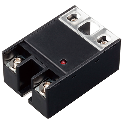
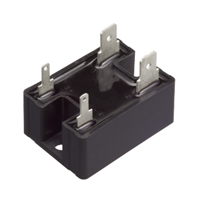
 AQ-A (AC output type) Solid State Relay
Load current up to Max. 40 A in the series, Small Screw Terminal SSR
AQ-A (AC output type) Solid State Relay
Load current up to Max. 40 A in the series, Small Screw Terminal SSR
-
 AQ-A (DC output type) Solid State Relay
Small Screw Terminal SSR Ideal for DC Control
AQ-A (DC output type) Solid State Relay
Small Screw Terminal SSR Ideal for DC Control
-
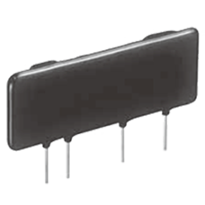
 AQ-G Solid State Relay
Slim type SSR for 1 A and 2 A control
AQ-G Solid State Relay
Slim type SSR for 1 A and 2 A control
-
 AQ-H Solid State Relay
Compact DIP type SSR Ideal for AC load control
AQ-H Solid State Relay
Compact DIP type SSR Ideal for AC load control
-
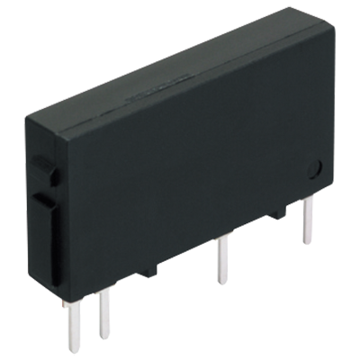
 AQ-J Solid State Relay
Small tab terminal SSR, Slim heat sink combined type also available
AQ-J Solid State Relay
Small tab terminal SSR, Slim heat sink combined type also available
-
- CAD data Catalogs/Datasheets
- FAQ
|
Rating
1.Ratings (Test sample: AQ-J stand-alone, Measurement condition: at 20℃, input ripple: 1% or less)
| Item | Part No. | Remarks | |||
|---|---|---|---|---|---|
| AQJ112V AQJ212V AQJ412V |
AQJ119V AQJ219V AQJ419V |
AQJ116V AQJ216V AQJ416V |
|||
| Input side | Rated voltage | 5 V DC | 12 V DC | 24 V DC | *1 |
| Control voltage | 4 to 6 V DC | 10 to 18 V DC | 18 to 28 V DC | ||
| Input impedance(Approx.) | 0.26 kΩ | 0.8 kΩ | 1.6 kΩ | ||
| Drop-out voltage | Min. 1 V DC | ||||
| Output side | Max. load current *2 | 10 A | 15 A | 25 A | |
| Load voltage | 75 to 264 Vrms | ||||
| Frequency | 45 to 65 Hz | ||||
| Non-repetitive surge current *3 | 100 A | 150 A | 250 A | In one cycle at 60 Hz | |
| “OFF-state” leakage current | Max. 5 mA | ||||
| “ON-state” voltage drop | Max. 1.6 V | ||||
| Min. load current *4 | 50 mA | ||||
| *1 | Refer to REFERENCE DATA “3. Input current vs. input voltage characteristics”. |
|---|---|
| *2 | Refer to REFERENCE DATA “1. Load current vs. ambient temperature characteristics”. |
| *3 | Refer to REFERENCE DATA “2. Non-repetitive surge current vs. carrying time”. |
| *4 | When the load current is less than the rated minimum load current, please refer to “Cautions for Use of Solid State Relays”. |
2.Ratings (AQ-J slim heat sink combined type, Measurement condition: at 20℃, input ripple: 1 % or less)
Input side
| Item | Part No. | Remarks | ||
|---|---|---|---|---|
| AQJ112V (Y ·W) AQJ412V (Y ·W) |
AQJ119V (Y ·W) AQJ419V (Y ·W) |
AQJ116V (Y ·W) AQJ416V (Y ·W) |
||
| Rated voltage | 5 V DC | 12 V DC | 24 V DC | *1 |
| Control voltage | 4 to 6 V DC | 10 to 18 V DC | 18 to 28 V DC | |
| Input impedance(Approx.) | 0.26 kΩ | 0.8 kΩ | 1.6 kΩ | |
| Drop-out voltage | Min. 1 V DC | |||
Output side
| Item | Part No. | Remarks | |||
|---|---|---|---|---|---|
| AQJ112VY AQJ119VY AQJ116VY |
AQJ412VY AQJ419VY AQJ416VY |
AQJ112VW AQJ119VW AQJ116VW |
AQJ412VW AQJ419VW AQJ416VW |
||
| Output arrangement | 1 Form A | 1 Form A × 2 | |||
| Max. load current *2 | 10 A | 20 A | 10 A | 15 A | |
| Load voltage | 75 to 264 Vrms | ||||
| Frequency | 45 to 65 Hz | ||||
| Non-repetitive surge current *3 | 100 A | 250 A | 100 A | 250 A | In one cycle at 60 Hz |
| “OFF-state” leakage current | Max. 5 mA | ||||
| “ON-state” voltage drop | Max. 1.6 V | ||||
| Min. load current *4 | 50 mA | ||||
| *1 | Refer to REFERENCE DATA “3. Input current vs. input voltage characteristics”. |
|---|---|
| *2 | Refer to REFERENCE DATA “1. Load current vs. ambient temperature characteristics”. |
| *3 | Refer to REFERENCE DATA “2. Non-repetitive surge current vs. carrying time”. |
| *4 | When the load current is less than the rated minimum load current, please refer to “Cautions for Use of Solid State Relays”. |
Characteristics (Measurement condition: at 20℃, input ripple: 1% or less)
| Item | Characteristics | Remarks |
|---|---|---|
| Operate time | Max. 1/2 cycle of voltage sine wave + 1 ms | |
| Release time | Max. 1/2 cycle of voltage sine wave + 1 ms | |
| Insulation resistance | Min. 100 MΩ between input, output and case | at 500 V DC |
| Breakdown voltage | 3,000 Vrms between input and output | for 1 minute |
| 2,500 Vrms between input, output and case | ||
| Vibration resistance | SSR stand-alone : Slim heat sink combined type : 10 to 55 Hz, double amplitude of 1.5 mm 10 to 55 Hz, double amplitude of 0.75 mm |
X, Y, Z axes |
| Shock resistance | SSR stand-alone : Slim heat sink combined type : Min. 980 m/s² Min. 197 m/s² |
X, Y, Z axes |
| Ambient temperature | − 30 to + 80℃ | Non-icing and non-condensing |
| Storage temperature | − 30 to + 100℃ | Non-icing and non-condensing |
| Operational method | Zero-cross (Turn ON and Turn OFF) |
|
BY EMAIL
- U.S.A.
- +1-800-344-2112
- Europe
- +49-89-45354-1000
- China
- +86-10-59255988
- Singapore
- +65-6299-9181


Requests to customers (Automation Control Components & Industrial Device) [Excluding specific product]
Requests to customers (Automation Control Components & Industrial Device) [For specific product]
Requests to customers (FA Sensors & Components [Excluding motors])
Requests to customers (Dedicated to industrial motors)
- COMPONENTS & DEVICES
- FA SENSORS & COMPONENTS
- Fiber Sensors
- Photoelectric Sensors / Laser Sensors
- Micro Photoelectric Sensors
- Light Curtains / Safety Components
- Area Sensors
- Inductive Proximity Sensors
- Particular Use Sensors
- Sensor Options
- Wire-Saving Systems
- Programmable Controllers / Interface Terminal
- Human Machine Interface
- Pressure Sensors / Flow Sensors
- Measurement Sensors
- Static Control Devices
- Laser Markers / 2D Code Readers
- Machine Vision System
- Energy Management Solutions
- Timers / Counters / FA Components
- MOTORS
![]()