[System Maintenance Notice]
Due to ongoing system maintenance, the site search and specification search functions are temporarily unavailable. We apologize for any inconvenience this may cause and appreciate your understanding.

 Business
> Industrial Devices
> Automation Controls Top
> Components & Devices
> Relays / Couplers
> Solid State Relays
> SSR Technical Terminology
Business
> Industrial Devices
> Automation Controls Top
> Components & Devices
> Relays / Couplers
> Solid State Relays
> SSR Technical Terminology
SSR Technical Terminology
1. Terminology of Phototriac Coupler/AQ-H
| Term | Symbol | Description | |
|---|---|---|---|
| Input side | LED forward current | IF | Current that flows between the input terminals when the input diode is forward biased. |
| LED reverse voltage | VR | Reverse breakdown voltage between the input terminals. | |
| Peak forward current | IFP | Maximum instantaneous value of the forward current. | |
| LED dropout voltage | VF | Dropout voltage between the input terminals due to forward current. | |
| Output side | Repetitive peak OFF-state voltage | VDRM | Maximum voltage with repeatability that can be applied continuously between the output terminals. |
| ON-state RMS current | IT(RMS) | Effective current value, based on designated conditions, that can flow continuously between output terminals. | |
| Non-repetitive surge current | ITSM | Maximum current, without repeatability, that is based on designated conditions. Normally this is expressed as the wave height value of one power frequency current sinusoidal cycle. |
|
| Peak ON-state voltage | VTM | Effective value of the voltage drop when a regulated load current flows between the output terminals when device is on. | |
| Peak OFF-state current | IDRM | Current that flows to output when a regulated load voltage is applied between the output terminals when device is off. | |
| Electrical Characteristics |
Trigger LED current | IFT | Current flow when LED current is augmented and output is on, when regulated power supply voltage and load has been connected between the output terminals. |
| Holding current | IH | Load current to maintain on state after output terminals have been turned on based on designated conditions. | |
| Critical rate of rise of OFF-state voltage | dv/dt | Output terminals do not go to the on state from the off state based on designated conditions. | |
| Zero-cross voltage | VZC | In the zero-cross method, when input is turned on, the maximum voltage value when the output terminals turn on. | |
| Turn on time | Ton | Delay time until the output switches on after a designated LED current is made to flow through the input terminals. | |
| I/O capacitance | Ciso | Capacitance between the input and output terminals. | |
| I/O isolation resistance | Riso | Resistance between terminals (input and output) when a specified voltage is applied between the input and output terminals. | |
2. Terminology of SSR
| Term | Description | |
|---|---|---|
| Input side | Control voltage | Input voltage necessary for normal SSR operation under the specified temperature conditions. |
| Activation voltage | Threshold at which the output turns on as the control voltage is gradually increased with the specified voltage applied to the loaded output. | |
| Recovery voltage | Threshold at which the output turns off as the control voltage is gradually decreased with the specified voltage applied to the loaded output. | |
| Input impedance | Resistance of the current limiting resistor used in the SSR input side. | |
| Input current | Input current at which an input module SSR operates normally. | |
| Load side | Max. load current | Maximum continuous current allowable across the SSR output terminals under the specified heat dissipation and ambient temperature conditions. AC current is specified in RMS units. |
| Load voltage | Output supply voltage range in which the SSR operates normally. AC voltage is specified in RMS units. | |
| Non-repetitive surge current | Maximum non-repetitive load current allowable under the specified heat dissipation and ambient temperature conditions. In general, it is given by the peak value of a single cycle of sinusoidal commercial AC current. | |
| “OFF-state” leakage current | Current that flows in the SSR output circuit when the specified supply voltage is applied to the output with no control voltage applied to the input. | |
| “ON-state” voltage drop | Output voltage drop caused by a specified load current supplied to the SSR output which is turned on by a specified input control voltage. AC voltage is specified in RMS units. | |
| On resistance | Resistance value (Ron) between the output terminals when the designated continuous load current (IL) is electrified through the output terminals. Obtained using the equation below from continuous load current (IL) and dropout voltage VDS (on) between the output terminals Ron = VDS (on)/IL | |
| Min. load current | Minimum load current at and above which the SSR operates normally under the specified temperature conditions. AC load current is specified in RMS units. | |
| Repetitive peak voltage, max. | Maximum repetitive voltage which can be continuously applied across the SSR output terminals. In general, a voltage of more than 400 V AC is used for 100 V AC applications, and more than 600 V AC for 200-250 V AC applications, to absorb supply voltage variations or on/off surges. | |
| Critical turn-off voltage rise ratio | SSRs may turn on if a turn-off voltage with a steep rising edge is applied. This phenomenon is called “dv/dt turn on.” Critical turn-off voltage rise ratio refers to the maximum turn-off voltage rise ratio at and below which the SSR remains turned off. | |
| Max. power dissipation | Allowable power dissipation between the output terminals. | |
| Electrical Characteristics |
Operate time, max. | Time until the SSR output turns on after the specified control voltage is applied to the input. |
| Release time, max. | Time until the SSR output turns off after the specified control voltage is removed from the input. | |
| Insulation resistance | Resistance measured with a specified voltage applied across the input and output, or across the input or output and frame ground. | |
| Breakdown voltage | Maximum voltage below which no dielectric breakdown occurs when applied for 1 minute across the same test points as those used for insulation resistance testing. | |
| Vibration resistance | Functional: The device sustains no damage and meets the specifications if it is exposed to vibration with its magnitude not exceeding this threshold during transit or installation. Destructive: Closed contacts of a relay remain closed for the specified time period if it is exposed to vibration with its magnitude not exceeding this threshold during operation. |
|
| Shock resistance | Functional: The device sustains no damage and meets the specifications if it is exposed to physical impact with its magnitude not exceeding this threshold during transit or installation. Destructive: Closed contacts of a relay remain closed for the specified time period if it is exposed to physical impact with its magnitude not exceeding this threshold during operation. |
|
| Ambient temperature | Ambient temperature range over which the SSR operates normally under the specified heat dissipation and load current conditions. | |
| Storage temperature | Ambient temperature range over which an SSR can be safely stored for extended periods without sustaining damage or performance degradation. | |
| Maximum switching frequency | Maximum switching frequency at which a SSR can operate normally when applying the specified pulse input to the input terminal | |
Catalog Download
|
|
Title | Language | File size | Update |
|---|---|---|---|---|
| フォトトライアックカプラ、AQ-H用語説明 フォトトライアックカプラ、AQ-H |
JP | 142.8KB | April 1, 2022 | |
| Terminology of Phototriac Coupler/AQ-H Phototriac coupler and AQ-H |
EN | 47.9KB | April 1, 2022 | |
| SSD用语的说明 | CN-Simplified | 457.5KB | August 22, 2019 |
CONTACT US
BY EMAIL
BY EMAIL
Please click your area to select country or region
BY PHONE
- U.S.A.
- +1-800-344-2112
- Europe
- +49-89-45354-1000
- China
- +86-10-59255988
- Singapore
- +65-6299-9181


Solid State Relays
-
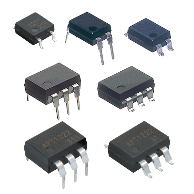
Phototriac Coupler Phototriac coupler for the industrial machinery and consumer electronics -
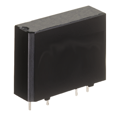
AQ1 Solid State Relay High capacity up to 3 A/10 A PC board terminal type -
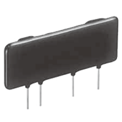
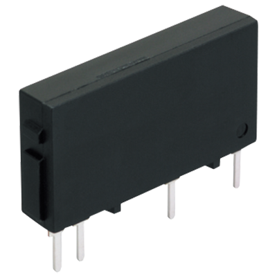
AQ8 Solid State Relay SIL type with 9 mm thickness, 3,000 V AC high dielectric voltage, controls up to 2 A/3 A -

AQ-A (AC output type) Solid State Relay Load current up to Max. 40 A in the series, Small Screw Terminal SSR -
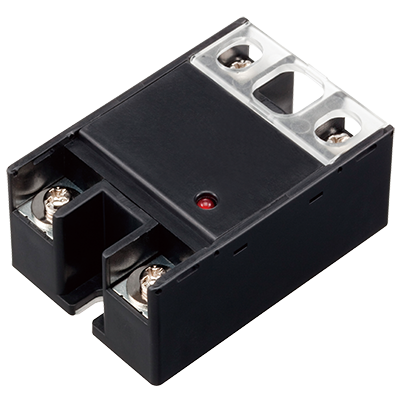
AQ-A (DC output type) Solid State Relay Small Screw Terminal SSR Ideal for DC Control -
AQ-G Solid State Relay Slim type SSR for 1 A and 2 A control -
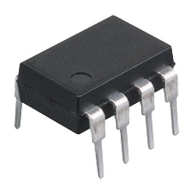
AQ-H Solid State Relay Compact DIP type SSR Ideal for AC load control -
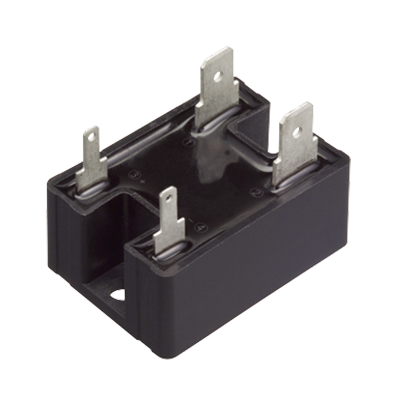
AQ-J Solid State Relay Small tab terminal SSR, Slim heat sink combined type also available
Related Information
Service & Support
Requests to customers (Automation Control Components & Industrial Device) [Excluding specific product]
Requests to customers (Automation Control Components & Industrial Device) [For specific product]
Requests to customers (FA Sensors & Components [Excluding motors])
Requests to customers (Dedicated to industrial motors)
- COMPONENTS & DEVICES
- FA SENSORS & COMPONENTS
- Fiber Sensors
- Photoelectric Sensors / Laser Sensors
- Micro Photoelectric Sensors
- Light Curtains / Safety Components
- Area Sensors
- Inductive Proximity Sensors
- Particular Use Sensors
- Sensor Options
- Wire-Saving Systems
- Programmable Controllers / Interface Terminal
- Human Machine Interface
- Pressure Sensors / Flow Sensors
- Measurement Sensors
- Static Control Devices
- Laser Markers / 2D Code Readers
- Machine Vision System
- Energy Management Solutions
- Timers / Counters / FA Components
- MOTORS
![]()