[System Maintenance Notice]
Due to ongoing system maintenance, the site search and specification search functions are temporarily unavailable. We apologize for any inconvenience this may cause and appreciate your understanding.

 Business
> Industrial Devices
> Automation Controls Top
> Components & Devices
> Relays / Couplers
> Microwave Devices
> Microwave Devices Lineup
> RD Coaxial Switches
> Rating/Performance
Business
> Industrial Devices
> Automation Controls Top
> Components & Devices
> Relays / Couplers
> Microwave Devices
> Microwave Devices Lineup
> RD Coaxial Switches
> Rating/Performance
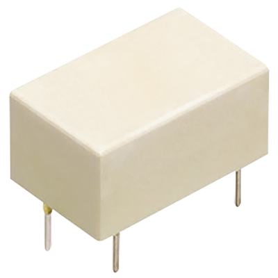
RD Coaxial Switches
-
Lineup
-
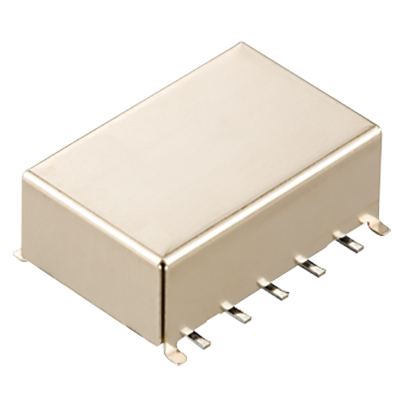 RA Relays
1 GHz capable, 3 W carrying power (at 1 GHz), 50 Ω, 2 Form C relays
RA Relays
1 GHz capable, 3 W carrying power (at 1 GHz), 50 Ω, 2 Form C relays
-
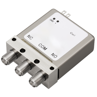 RD Coaxial Switches
26.5 GHz max. coaxial switches coming in SPDT, Transfer, and SP6T types
RD Coaxial Switches
26.5 GHz max. coaxial switches coming in SPDT, Transfer, and SP6T types
-
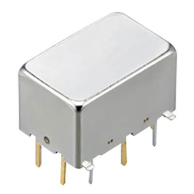 RJ Relays
8 GHz max. capable, 1 W carrying power ( at 5 GHz ), 50 Ω impedance and 2 Form C relays
RJ Relays
8 GHz max. capable, 1 W carrying power ( at 5 GHz ), 50 Ω impedance and 2 Form C relays
-
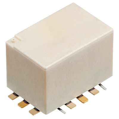 RN Relays
8 GHz max. capable, 150 W carrying power ( at 2 GHz ), compact SMD type, 50 Ω impedance and 1 Form C relays
RN Relays
8 GHz max. capable, 150 W carrying power ( at 2 GHz ), compact SMD type, 50 Ω impedance and 1 Form C relays
-
 RS Relays
3 GHz capable, 10 W carrying power (at 3 GHz), 50/75 Ω, 1 Form C Relays
RS Relays
3 GHz capable, 10 W carrying power (at 3 GHz), 50/75 Ω, 1 Form C Relays
-
- CAD data Catalogs/Datasheets
- FAQ
|
Coil data
- Operating characteristics such as "Operate voltage" and "Release voltage" are influenced by mounting conditions, ambient temperature, etc. Therefore, please use the relay within ±5% of rated coil voltage.
- "Initial" means the condition of products at the time of delivery.
● SPDT
Fail-safe
| Rated coil voltage | Rated operating current (+10%/-15%, at 20°C) |
Rated operating power | ||
|---|---|---|---|---|
| With indicator | Without indicator | With indicator | Without indicator | |
| 4.5 V DC | 186.7 mA | 155.6 mA | 840 mW | 700 mW |
| 12 V DC | 70.0 mA | 58.3 mA | ||
| 24 V DC | 38.8 mA | 29.2 mA | 930 mW | |
Latching
| Rated coil voltage | Rated operating current (+10%/-15%, at 20°C) |
Rated operating power | ||
|---|---|---|---|---|
| With indicator | Without indicator | With indicator | Without indicator | |
| 4.5 V DC | 133.3 mA | 111.1 mA | 600 mW | 500 mW |
| 12 V DC | 50.0 mA | 41.7 mA | ||
| 24 V DC | 25.8 mA | 16.7 mA | 620 mW | |
Latching with TTL drive
| Rated coil voltage | TTL logic level* | Self cut-off function | Switching frequency | |
|---|---|---|---|---|
| ON | OFF | |||
| 5 V DC | 2.4 to 5.5 V (Square wave) | 0 to 0.5 V (Square wave) | Available | Max.180 times/min (ON : OFF = 1 : 1) |
| 12 V DC | ||||
| 24 V DC | ||||
* Please see Operating voltage range.
● Transfer
Fail-safe
| Rated coil voltage | Rated operating current (+10%/-15%, at 20°C) |
Rated operating power |
|---|---|---|
| 4.5 V DC | 342.2 mA | 1,540 mW |
| 12 V DC | 128.3 mA | |
| 24 V DC | 67.92 mA | 1,630 mW |
Latching
| Rated coil voltage | Rated operating current (+10%/-15%, at 20°C) |
Rated operating power |
|---|---|---|
| 4.5 V DC | 244.4 mA | 1,100 mW |
| 12 V DC | 91.7 mA | |
| 24 V DC | 46.7 mA | 1,120 mW |
Latching with TTL driver
| Rated coil voltage | TTL logic level* | Self cut-off function | Switching frequency | |
|---|---|---|---|---|
| ON | OFF | |||
| 5 V DC | 4.5 to 5.5 V (Square wave) | 0 to 0.5 V (Square wave) | Available | Max.180 times/min (ON : OFF = 1 : 1) |
| 12 V DC | ||||
| 24 V DC | ||||
* Please see Operating voltage range.
● SP6T
Fail-safe
| Rated coil voltage | Rated operating current (+10%/-15%, at 20°C) |
Rated operating power |
|---|---|---|
| 4.5 V DC | 186.7 mA | 840 mW |
| 12 V DC | 70.0 mA | |
| 24 V DC | 38.8 mA | 930 mW |
Latching
| Rated coil voltage | Rated operating current (+10%/-15%, at 20°C) |
Rated operating power |
|---|---|---|
| 4.5 V DC | SET 133.3 mA/RESET (ALL) 800 mA | SET 600 mW/RESET (ALL) 3,600 mW |
| 12 V DC | SET: 50.0 mA/RESET (ALL): 300 mA | |
| 24 V DC | SET: 25.8 mA / RESET (ALL): 155 mA | SET: 620 mW / RESET (ALL): 3,720 mW |
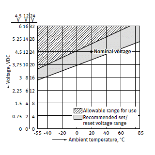
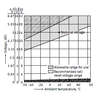
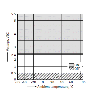
Operating voltage range
Fail-safe type
|

Latching type
|
Latching with TTL driver type (with self cut-off function)
|
TTL Logic level range
|
| * | Please consult us for use that is outside this range. |
|---|
SPDT, Transfer
Specifications
| Item | Specifications | ||
|---|---|---|---|
| Contact data | Contact arrangement | SPDT | Transfer |
| Contact resistance (initial) | Max. 100 mΩ (by voltage drop 6 V DC 1 A) | ||
| Contact material | Au plating | ||
| Contact input power (CW) | Max. 120 W (at 40°C, 3 GHz, 50 Ω, V.S.W.R. Max. 1.15, no contact switching) |
Max. 120 W (at 25°C, 3 GHz, 50 Ω, V.S.W.R. Max. 1.15, no contact switching) |
|
| Indicator rating*1 | Contact resistance (initial) | Max. 1 Ω (at 5 V 100 mA) | |
| Max. switching voltage | 30 V DC | ||
| Max. switching current | 100 mA | ||
| Insulation resistance (initial) | Min. 1,000 MΩ (at 500 V DC, Measured portion is the same as the case of dielectric strength.) | ||
| Dielectric strength (initial) | Between open contacts | 500 Vrms for 1 min (detection current: 10 mA) | |
| Between contact and coil | 500 Vrms for 1 min (detection current: 10 mA) | ||
| Between contact and earth terminal | 500 Vrms for 1 min (detection current: 10 mA) | ||
| Between coil and earth terminal | 500 Vrms for 1 min (detection current: 10 mA) | ||
| Time characteristics (initial) | Operate (Set) time | Max. 15 ms at rated coil voltage (at 20°C, without bounce) |
Max. 20 ms at rated coil voltage (at 20°C, without bounce) |
| Release (Reset) time | - | Max. 20 ms at rated coil voltage (at 20°C, without bounce) |
|
| Operate bounce time | Max. 10 ms (at 20°C) | - | |
| Shock resistance | Functional | 500 m/s2 (half-sine shock pulse: 11 ms, detection time: 10 μs) | |
| Destructive | 1,000 m/s2 (half-sine shock pulse: 11 ms) | ||
| Vibration resistance | Functional | 10 to 55 Hz (at double amplitude of 3 mm, detection time: 10 μs) | |
| Destructive | 10 to 55 Hz (at double amplitude of 5 mm) | ||
| Expected life | Mechanical life (Cold switch) |
6 GHz: Min. 106 18 and 26.5 GHz: Min. 5 x 10⁶ (switching frequency: 180 times/min) |
Min. 5 x 10⁶ (switching frequency: 180 times/min) |
| Conditions | Conditions for usage, transport and storage*2 | Ambient temperature: -55 to +85°C Humidity: 5 to 85% RH (Avoid icing and condensation) |
|
| Unit weight | Approx. 50 g | Approx. 110 g | |
| *1 | With indicator type only |
|---|---|
| *2 | For ambient temperature, please read "GUIDELINES FOR RELAY USAGE". |
Expected electrical life (hot switch)
Conditions: Switching frequency 20 times/min
| Type | Load | Switching capacity | Number of operations |
|---|---|---|---|
| SPDT | 18 and 26.5 GHz high frequency load | 5 W (Up to 3 GHz, 50 Ω, V.S.W.R. Max. 1.2) | Min. 5 x 10⁶ |
| Indicator | 10 mA 5 V DC | Min. 5 x 10⁶ | |
| 6 GHz high frequency load | 5 W (Up to 3 GHz, 50 Ω, V.S.W.R. Max. 1.2) | Min. 106 | |
| Indicator | 10 mA 5 V DC | Min. 106 | |
| Transfer | High frequency load | 5 W (Up to 3 GHz, 50 Ω, V.S.W.R. Max. 1.2) | Min. 5 x 10⁶ |
| Indicator | 10 mA 5 V DC | Min. 5 x 10⁶ |
SP6T
Specifications
| Item | Specifications | |
|---|---|---|
| Contact data | Contact arrangement | SP6T |
| Contact resistance (initial) | Max. 100 mΩ (by voltage drop 6 V DC 1 A) | |
| Contact material | Au plating | |
| Contact input power (CW) | Max. 120 W (at 25°C, 3 GHz, 50 Ω, V.S.W.R. Max. 1.15, no contact switching) | |
| Indicator rating | Contact resistance (initial) | Max. 1 Ω (at 5 V 100 mA) |
| Max. switching voltage | 30 V DC | |
| Max. switching current | 100 mA | |
| Insulation resistance (initial) | Min. 1,000 MΩ (at 500 V DC, Measured portion is the same as the case of dielectric strength.) | |
| Dielectric strength (initial) | Between open contacts | 500 Vrms for 1 min (detection current: 10 mA) |
| Between contact and coil | 500 Vrms for 1 min (detection current: 10 mA) | |
| Between contact and earth terminal | 500 Vrms for 1 min (detection current: 10 mA) | |
| Between coil and earth terminal | 500 Vrms for 1 min (detection current: 10 mA) | |
| Time characteristics (initial) | Operate (Set) time | Max. 20 ms at rated coil voltage (at 20°C, without bounce) |
| Release (Reset) time | Max. 20 ms at rated coil voltage (at 20°C, without bounce) | |
| Shock resistance | Functional | 500 m/s2 (half-sine shock pulse: 11 ms, detection time: 10 μs) |
| Destructive | 1,000 m/s2 (half-sine shock pulse: 11 ms) | |
| Vibration resistance | Functional | 10 to 55 Hz (at double amplitude of 3 mm, detection time: 10 μs) |
| Destructive | 10 to 55 Hz (at double amplitude of 5 mm) | |
| Expected life | Mechanical life (Cold switch) | Min. 5 x 10⁶ (switching frequency: 180 times/min) |
| Conditions | Conditions for usage, transport and storage* | Ambient temperature: -55 to +85°C Humidity: 5 to 85% RH (Avoid icing and condensation) |
| Unit weight | Approx. 320 g | |
* For ambient temperature, please read “GUIDELINES FOR RELAY USAGE”.
Expected electrical life (hot switch)
Conditions: Switching frequency 20 times/min
| Type | Switching capacity | Number of operations | |
|---|---|---|---|
| SP6T | Contact | 5 W (Up to 3 GHz, 50 Ω, V.S.W.R. Max. 1.2) | Min. 5 x 10⁶ |
| Indicator | 10 mA 5 V DC | Min. 5 x 10⁶ | |
|
BY EMAIL
- U.S.A.
- +1-800-344-2112
- Europe
- +49-89-45354-1000
- China
- +86-10-59255988
- Singapore
- +65-6299-9181


Requests to customers (Automation Control Components & Industrial Device) [Excluding specific product]
Requests to customers (Automation Control Components & Industrial Device) [For specific product]
Requests to customers (FA Sensors & Components [Excluding motors])
Requests to customers (Dedicated to industrial motors)
- COMPONENTS & DEVICES
- FA SENSORS & COMPONENTS
- Fiber Sensors
- Photoelectric Sensors / Laser Sensors
- Micro Photoelectric Sensors
- Light Curtains / Safety Components
- Area Sensors
- Inductive Proximity Sensors
- Particular Use Sensors
- Sensor Options
- Wire-Saving Systems
- Programmable Controllers / Interface Terminal
- Human Machine Interface
- Pressure Sensors / Flow Sensors
- Measurement Sensors
- Static Control Devices
- Laser Markers / 2D Code Readers
- Machine Vision System
- Energy Management Solutions
- Timers / Counters / FA Components
- MOTORS
![]()